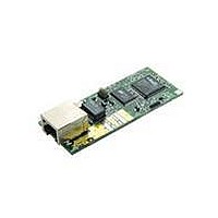
101-0681 Rabbit Semiconductor, 101-0681 Datasheet - Page 5

101-0681
Manufacturer Part Number
101-0681
Description
KIT DEVELOPMENT RCM3700 INT'L
Manufacturer
Rabbit Semiconductor
Series
RabbitCore 3000r
Type
MPU Moduler
Datasheet
1.101-0522.pdf
(169 pages)
Specifications of 101-0681
Contents
RabbitCore Module, Dev. Board, AC Adapter, Cable and Dynamic C® CD-Rom
Processor To Be Evaluated
Rabbit 3000
Interface Type
Ethernet
Maximum Operating Temperature
+ 70 C
Minimum Operating Temperature
- 40 C
Operating Supply Voltage
4.75 V to 5.25 V
For Use With/related Products
RCM3700
Lead Free Status / RoHS Status
Contains lead / RoHS non-compliant
Other names
101-681
101-681
101-681
Available stocks
Company
Part Number
Manufacturer
Quantity
Price
Company:
Part Number:
101-0681
Manufacturer:
Rabbit
Quantity:
201
Appendix C. LCD/Keypad Module
Appendix D. Power Supply
Appendix E. Secure Embedded Web Application Kit
Index
Schematics
RabbitCore RCM3700 User’s Manual
B.2 RCM3720 Prototyping Board ..........................................................................................................112
C.1 Specifications ...................................................................................................................................123
C.2 Contrast Adjustments for All Boards ...............................................................................................125
C.3 Keypad Labeling ..............................................................................................................................126
C.4 Header Pinouts .................................................................................................................................127
C.5 Install Connectors on Prototyping Board .........................................................................................128
C.6 Mounting LCD/Keypad Module on the Prototyping Board ............................................................129
C.7 Bezel-Mount Installation..................................................................................................................130
C.8 Sample Programs .............................................................................................................................133
C.9 LCD/Keypad Module Function Calls ..............................................................................................134
D.1 Power Supplies.................................................................................................................................158
E.1 Sample Programs..............................................................................................................................162
E.2 Module Documentation ....................................................................................................................162
B.1.6 Serial Communication..............................................................................................................103
B.1.7 Other Prototyping Board Modules ...........................................................................................107
B.1.8 Jumper Configurations .............................................................................................................108
B.1.9 Use of Rabbit 3000 Parallel Ports ............................................................................................110
B.2.1 Features ....................................................................................................................................113
B.2.2 Mechanical Dimensions and Layout ........................................................................................114
B.2.3 Power Supply ...........................................................................................................................115
B.2.4 Using the RCM3720 Prototyping Board ..................................................................................116
B.2.5 Serial Communication..............................................................................................................119
B.2.6 Use of Rabbit 3000 Parallel Ports ............................................................................................121
C.4.1 I/O Address Assignments .........................................................................................................127
C.7.1 Connect the LCD/Keypad Module to Your Prototyping Board...............................................132
C.9.1 LCD/Keypad Module Initialization..........................................................................................134
C.9.2 LEDs.........................................................................................................................................134
C.9.3 LCD Display.............................................................................................................................135
C.9.4 Keypad......................................................................................................................................155
D.1.1 Battery Backup.........................................................................................................................159
D.1.2 Battery-Backup Circuit ............................................................................................................160
D.1.3 Reset Generator ........................................................................................................................160
B.1.6.1 RS-232 ............................................................................................................................. 104
B.1.6.2 RS-485 ............................................................................................................................. 105
B.2.4.1 Prototyping Area.............................................................................................................. 118
123
158
161
163
167
3


