DEMO56F8014-EE Freescale Semiconductor, DEMO56F8014-EE Datasheet - Page 113
DEMO56F8014-EE
Manufacturer Part Number
DEMO56F8014-EE
Description
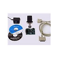
BOARD DEMO FOR 56F8014
Manufacturer
Freescale Semiconductor
Type
MCUr
Datasheets
1.CWH-UTP-ONCE-HE.pdf
(2 pages)
2.APMOTOR56F8000E.pdf
(124 pages)
3.DEMO56F8013-EE.pdf
(2 pages)
Specifications of DEMO56F8014-EE
Contents
*
Processor To Be Evaluated
MC56F8014
Data Bus Width
16 bit
Interface Type
RS-232
For Use With/related Products
56F8014
For Use With
APMOTOR56F8000E - KIT DEMO MOTOR CTRL SYSTEM
Lead Free Status / RoHS Status
Lead free / RoHS Compliant


10.15 Equivalent Circuit for ADC Inputs
Figure 10-17
at the same time that S3 is closed/open. When S1/S2 are closed & S3 is open, one input of the sample and
hold circuit moves to (V
switches are flipped, the charge on C1 and C2 are averaged via S3, with the result that a single-ended
analog input is switched to a differential voltage centered about (V
on every cycle of the ADC clock (open one-half ADC clock, closed one-half ADC clock). Note that there
are additional capacitances associated with the analog input pad, routing, etc., but these do not filter into
the S/H output voltage, as S1 provides isolation during the charge-sharing phase.
One aspect of this circuit is that there is an on-going input current, which is a function of the analog input
voltage, V
Freescale Semiconductor
5. LSB = Least Significant Bit = 0.806mV
6. Pin groups are detailed following
7. The current that can be injected or sourced from an unselected ADC signal input without impacting the performance of the
ADC.
REF
illustrates the ADC input circuit during sample and hold. S1 and S2 are always open/closed
and the ADC clock frequency.
REFH
-V
Table
REFL
10-1.
)/2, while the other charges to the analog input voltage. When the
56F8014 Technical Data, Rev. 11
REFH
-V
REFL
)/2. The switches switch
Equivalent Circuit for ADC Inputs
113
Related parts for DEMO56F8014-EE
Image
Part Number
Description
Manufacturer
Datasheet
Request
R

Part Number:
Description:
Manufacturer:
Freescale Semiconductor, Inc
Datasheet:
Part Number:
Description:
Manufacturer:
Freescale Semiconductor, Inc
Datasheet:
Part Number:
Description:
Manufacturer:
Freescale Semiconductor, Inc
Datasheet:
Part Number:
Description:
Manufacturer:
Freescale Semiconductor, Inc
Datasheet:
Part Number:
Description:
Manufacturer:
Freescale Semiconductor, Inc
Datasheet:
Part Number:
Description:
Manufacturer:
Freescale Semiconductor, Inc
Datasheet:
Part Number:
Description:
Manufacturer:
Freescale Semiconductor, Inc
Datasheet:
Part Number:
Description:
Manufacturer:
Freescale Semiconductor, Inc
Datasheet:
Part Number:
Description:
Manufacturer:
Freescale Semiconductor, Inc
Datasheet:
Part Number:
Description:
Manufacturer:
Freescale Semiconductor, Inc
Datasheet:
Part Number:
Description:
Manufacturer:
Freescale Semiconductor, Inc
Datasheet:
Part Number:
Description:
Manufacturer:
Freescale Semiconductor, Inc
Datasheet:
Part Number:
Description:
Manufacturer:
Freescale Semiconductor, Inc
Datasheet:
Part Number:
Description:
Manufacturer:
Freescale Semiconductor, Inc
Datasheet:
Part Number:
Description:
Manufacturer:
Freescale Semiconductor, Inc
Datasheet: