DEMO56F8014-EE Freescale Semiconductor, DEMO56F8014-EE Datasheet - Page 122
DEMO56F8014-EE
Manufacturer Part Number
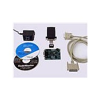
DEMO56F8014-EE
Description
BOARD DEMO FOR 56F8014
Manufacturer
Freescale Semiconductor
Type
MCUr
Datasheets
1.CWH-UTP-ONCE-HE.pdf
(2 pages)
2.APMOTOR56F8000E.pdf
(124 pages)
3.DEMO56F8013-EE.pdf
(2 pages)
Specifications of DEMO56F8014-EE
Contents
*
Processor To Be Evaluated
MC56F8014
Data Bus Width
16 bit
Interface Type
RS-232
For Use With/related Products
56F8014
For Use With
APMOTOR56F8000E - KIT DEMO MOTOR CTRL SYSTEM
Lead Free Status / RoHS Status
Lead free / RoHS Compliant


122
•
•
•
•
•
•
PCB trace lengths should be minimal for high-frequency signals
Consider all device loads as well as parasitic capacitance due to PCB traces when calculating capacitance.
This is especially critical in systems with higher capacitive loads that could create higher transient currents
in the V
Take special care to minimize noise levels on the V
Using separate power planes for V
recommended. Connect the separate analog and digital power and ground planes as close as possible to
power supply outputs. If both analog circuit and digital circuit are powered by the same power supply, it is
advisable to connect a small inductor or ferrite bead in serial with both V
It is highly desirable to physically separate analog components from noisy digital components by ground
planes. Do not place an analog trace in parallel with digital traces. It is also desirable to place an analog
ground trace around an analog signal trace to isolate it from digital traces.
Because the Flash memory is programmed through the JTAG/EOnCE port, SPI, SCI or I
should provide an interface to this port if in-circuit Flash programming is desired.
DD
and V
SS
circuits.
56F8014 Technical Data, Rev. 11
DD
and V
DDA
and separate ground planes for V
REF
, V
DDA
and V
SSA
DDA
pins
and V
SS
Freescale Semiconductor
SSA
and V
traces.
2
C, the designer
SSA
is
Related parts for DEMO56F8014-EE
Image
Part Number
Description
Manufacturer
Datasheet
Request
R

Part Number:
Description:
Manufacturer:
Freescale Semiconductor, Inc
Datasheet:
Part Number:
Description:
Manufacturer:
Freescale Semiconductor, Inc
Datasheet:
Part Number:
Description:
Manufacturer:
Freescale Semiconductor, Inc
Datasheet:
Part Number:
Description:
Manufacturer:
Freescale Semiconductor, Inc
Datasheet:
Part Number:
Description:
Manufacturer:
Freescale Semiconductor, Inc
Datasheet:
Part Number:
Description:
Manufacturer:
Freescale Semiconductor, Inc
Datasheet:
Part Number:
Description:
Manufacturer:
Freescale Semiconductor, Inc
Datasheet:
Part Number:
Description:
Manufacturer:
Freescale Semiconductor, Inc
Datasheet:
Part Number:
Description:
Manufacturer:
Freescale Semiconductor, Inc
Datasheet:
Part Number:
Description:
Manufacturer:
Freescale Semiconductor, Inc
Datasheet:
Part Number:
Description:
Manufacturer:
Freescale Semiconductor, Inc
Datasheet:
Part Number:
Description:
Manufacturer:
Freescale Semiconductor, Inc
Datasheet:
Part Number:
Description:
Manufacturer:
Freescale Semiconductor, Inc
Datasheet:
Part Number:
Description:
Manufacturer:
Freescale Semiconductor, Inc
Datasheet:
Part Number:
Description:
Manufacturer:
Freescale Semiconductor, Inc
Datasheet: