DEMO56F8014-EE Freescale Semiconductor, DEMO56F8014-EE Datasheet - Page 24
DEMO56F8014-EE
Manufacturer Part Number
DEMO56F8014-EE
Description
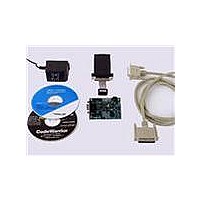
BOARD DEMO FOR 56F8014
Manufacturer
Freescale Semiconductor
Type
MCUr
Datasheets
1.CWH-UTP-ONCE-HE.pdf
(2 pages)
2.APMOTOR56F8000E.pdf
(124 pages)
3.DEMO56F8013-EE.pdf
(2 pages)
Specifications of DEMO56F8014-EE
Contents
*
Processor To Be Evaluated
MC56F8014
Data Bus Width
16 bit
Interface Type
RS-232
For Use With/related Products
56F8014
For Use With
APMOTOR56F8000E - KIT DEMO MOTOR CTRL SYSTEM
Lead Free Status / RoHS Status
Lead free / RoHS Compliant


24
Table 2-3 56F8014 Signal and Package Information for the 32-Pin LQFP (Continued)
Return to
(GPIOC0)
(GPIOC1)
(GPIOC2)
(GPIOC3)
(GPIOC4)
(V
Signal
Name
ANA0
ANA1
ANA2
ANA3
ANB0
REFH
)
Table 2-2
Pin No.
LQFP
13
12
11
10
4
Output
Output
Output
Output
Output
Input/
Input/
Input/
Input/
Input/
Type
Input
Input
Input
Input
Input
Input
State During
Analog
Analog
Analog
Analog
Analog
Reset
Input
Input
Input
Input
Input
56F8014 Technical Data, Rev. 11
ANA0 — Analog input to ADC A, channel 0
Port C GPIO — This GPIO pin can be individually programmed as
an input or output pin.
After reset, the default state is ANA0.
ANA1 — Analog input to ADC A, channel 1
Port C GPIO — This GPIO pin can be individually programmed as
an input or output pin.
After reset, the default state is ANA1.
ANA2 — Analog input to ADC A, channel 2
V
Port C GPIO — This GPIO pin can be individually programmed as
an input or output pin.
After reset, the default state is ANA2.
ANA3 — Analog input to ADC A, channel 3
Port C GPIO — This GPIO pin can be individually programmed as
an input or output pin.
After reset, the default state is ANA3.
ANB0 — Analog input to ADC B, channel 0
Port C GPIO — This GPIO pin can be individually programmed as
an input or output pin.
After reset, the default state is ANB0.
REFH
— Analog reference voltage high
Signal Description
Freescale Semiconductor
Related parts for DEMO56F8014-EE
Image
Part Number
Description
Manufacturer
Datasheet
Request
R

Part Number:
Description:
Manufacturer:
Freescale Semiconductor, Inc
Datasheet:
Part Number:
Description:
Manufacturer:
Freescale Semiconductor, Inc
Datasheet:
Part Number:
Description:
Manufacturer:
Freescale Semiconductor, Inc
Datasheet:
Part Number:
Description:
Manufacturer:
Freescale Semiconductor, Inc
Datasheet:
Part Number:
Description:
Manufacturer:
Freescale Semiconductor, Inc
Datasheet:
Part Number:
Description:
Manufacturer:
Freescale Semiconductor, Inc
Datasheet:
Part Number:
Description:
Manufacturer:
Freescale Semiconductor, Inc
Datasheet:
Part Number:
Description:
Manufacturer:
Freescale Semiconductor, Inc
Datasheet:
Part Number:
Description:
Manufacturer:
Freescale Semiconductor, Inc
Datasheet:
Part Number:
Description:
Manufacturer:
Freescale Semiconductor, Inc
Datasheet:
Part Number:
Description:
Manufacturer:
Freescale Semiconductor, Inc
Datasheet:
Part Number:
Description:
Manufacturer:
Freescale Semiconductor, Inc
Datasheet:
Part Number:
Description:
Manufacturer:
Freescale Semiconductor, Inc
Datasheet:
Part Number:
Description:
Manufacturer:
Freescale Semiconductor, Inc
Datasheet:
Part Number:
Description:
Manufacturer:
Freescale Semiconductor, Inc
Datasheet: