DEMO56F8014-EE Freescale Semiconductor, DEMO56F8014-EE Datasheet - Page 73
DEMO56F8014-EE
Manufacturer Part Number
DEMO56F8014-EE
Description
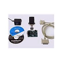
BOARD DEMO FOR 56F8014
Manufacturer
Freescale Semiconductor
Type
MCUr
Datasheets
1.CWH-UTP-ONCE-HE.pdf
(2 pages)
2.APMOTOR56F8000E.pdf
(124 pages)
3.DEMO56F8013-EE.pdf
(2 pages)
Specifications of DEMO56F8014-EE
Contents
*
Processor To Be Evaluated
MC56F8014
Data Bus Width
16 bit
Interface Type
RS-232
For Use With/related Products
56F8014
For Use With
APMOTOR56F8000E - KIT DEMO MOTOR CTRL SYSTEM
Lead Free Status / RoHS Status
Lead free / RoHS Compliant


6.3.8.6
This bit selects the alternate function for GPIOB5.
6.3.8.7
This bit selects the alternate function for GPIOB4.
6.3.8.8
This bit selects the alternate function for GPIOB3.
6.3.8.9
This bit selects the alternate function for GPIOB2.
6.3.8.10
This bit selects the alternate function for GPIOB1.
6.3.8.11
This bit selects the alternate function for GPIOB0.
6.3.8.12
These bits select the alternate function for GPIOA5.
Freescale Semiconductor
•
•
•
•
•
•
•
•
•
•
•
•
•
•
•
source clock to the chip. In this mode, make sure that no on-chip peripheral (including the
GPIO) is driving this pin.
0 = T1 — Timer channel 1 input/output (default)
1 = FAULT3 — PWM FAULT3 input
0 = T0 — Timer channel 0 input/output (default)
1 = CLKO — Clock output
0 = MOSI — SPI master out/slave in (default)
1 = T3 — Timer channel 3 input/output
0 = MISO — SPI master in/slave out (default)
1 = T2 — Timer channel 2 input/output
0 = SS — SPI Slave Select (default)
1 = SDA — I
0 = SCLK — SPI Serial Clock (default)
1 = SCL — I2C Serial Clock
00 = PWM5 — PWM5 output (default)
01 = PWM5 — PWM5 output
10 = FAULT2 — PWM FAULT2 input
Configure GPIOB5 (CFG_B5)—Bit 9
Configure GPIOB4 (CFG_B4)—Bit 8
Configure GPIOB3 (CFG_B3)—Bit 7
Configure GPIOB2 (CFG_B2)—Bit 6
Configure GPIOB1 (CFG_B1)—Bit 5
Configure GPIOB0 (CFG_B0)—Bit 4
Configure GPIOA5[1:0] (CFG_A5)—Bits 3–2
2
C Serial Data
56F8014 Technical Data, Rev. 11
Register Descriptions
73
Related parts for DEMO56F8014-EE
Image
Part Number
Description
Manufacturer
Datasheet
Request
R

Part Number:
Description:
Manufacturer:
Freescale Semiconductor, Inc
Datasheet:
Part Number:
Description:
Manufacturer:
Freescale Semiconductor, Inc
Datasheet:
Part Number:
Description:
Manufacturer:
Freescale Semiconductor, Inc
Datasheet:
Part Number:
Description:
Manufacturer:
Freescale Semiconductor, Inc
Datasheet:
Part Number:
Description:
Manufacturer:
Freescale Semiconductor, Inc
Datasheet:
Part Number:
Description:
Manufacturer:
Freescale Semiconductor, Inc
Datasheet:
Part Number:
Description:
Manufacturer:
Freescale Semiconductor, Inc
Datasheet:
Part Number:
Description:
Manufacturer:
Freescale Semiconductor, Inc
Datasheet:
Part Number:
Description:
Manufacturer:
Freescale Semiconductor, Inc
Datasheet:
Part Number:
Description:
Manufacturer:
Freescale Semiconductor, Inc
Datasheet:
Part Number:
Description:
Manufacturer:
Freescale Semiconductor, Inc
Datasheet:
Part Number:
Description:
Manufacturer:
Freescale Semiconductor, Inc
Datasheet:
Part Number:
Description:
Manufacturer:
Freescale Semiconductor, Inc
Datasheet:
Part Number:
Description:
Manufacturer:
Freescale Semiconductor, Inc
Datasheet:
Part Number:
Description:
Manufacturer:
Freescale Semiconductor, Inc
Datasheet: