5.07.01 FLASHER ARM Segger Microcontroller Systems, 5.07.01 FLASHER ARM Datasheet - Page 31
5.07.01 FLASHER ARM
Manufacturer Part Number
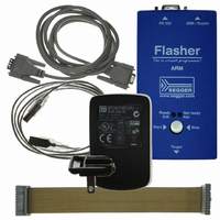
5.07.01 FLASHER ARM
Description
PROGRAMMER JTAG FOR ARM CORES
Manufacturer
Segger Microcontroller Systems
Type
In-System Programmerr
Specifications of 5.07.01 FLASHER ARM
Contents
Programmer
For Use With/related Products
ARM7, ARM9, Cortex
Lead Free Status / RoHS Status
Lead free / RoHS Compliant
Other names
899-1002


3.2
Flasher ARM (UM08007)
Flasher ARM can be remote controlled by automated testers without the need of a
connection to PC and Flasher ARM’s PC program. Therefore Flasher ARM is equipped
with additional hardware control functions, which are connected to the SUBD9 male
connector, normally used as RS232 interface to PC.
The following diagrams show the internal remote control circuitry of Flasher ARM:
Table 3.1: Flasher ARM LED status
1
4
5
7
Pin No.
BUSY
OK
START
Handshake control
START
BUSY
GND
OK
5
4
7
1
previous state
Function
OK
BUSY
START
A positive pulse of any voltage between 5 and 30V with dura-
tion of min. 30 ms starts “Auto” function (Clear / Program /
Verify) on falling edge of pulse. The behavior of the "Auto"
function depends on the project settings, chosen in J-Flash at
the Production tab.
As soon as the "Auto" function is started, BUSY becomes
active, which means that transistor is switched OFF.
Common Signal ground.
This output reflects result of last action. It is valid after BUSY
turned back to passive state. The output transistor is
switched ON to reflect OK state.
470
470
22k
4k7
Undefined
© 2004-2009 SEGGER Microcontroller GmbH & Co. KG
Description
valid
internal Logic
Flasher ARM
BUSY
Ready
Not OK
OK
31
Related parts for 5.07.01 FLASHER ARM
Image
Part Number
Description
Manufacturer
Datasheet
Request
R

Part Number:
Description:
CONNECTOR JTAG-ARM ISOLATION
Manufacturer:
Segger Microcontroller Systems
Datasheet:

Part Number:
Description:
ADAPTER ARM TARGET 14PIN RIBBON
Manufacturer:
Segger Microcontroller Systems
Datasheet:

Part Number:
Description:
JTAG EMULATOR FOR ARM CORES
Manufacturer:
Segger Microcontroller Systems
Datasheet:

Part Number:
Description:
JTAG EMULATOR FOR ARM CORES
Manufacturer:
Segger Microcontroller Systems
Datasheet:

Part Number:
Description:
PROGRAMMING TOOL FOR MCU
Manufacturer:
Segger Microcontroller Systems
Datasheet:

Part Number:
Description:
PROGRAMMING TOOL FOR ST7 MCU
Manufacturer:
Segger Microcontroller Systems
Datasheet:

Part Number:
Description:
PROGRAMMING TOOL FOR STM8
Manufacturer:
Segger Microcontroller Systems
Datasheet:

Part Number:
Description:
JTAG EMULATOR USB ETHERNET ARM
Manufacturer:
Segger Microcontroller Systems
Datasheet:

Part Number:
Description:
JTAG EMULATOR ARM7/ARM9 ETM
Manufacturer:
Segger Microcontroller Systems
Datasheet:

Part Number:
Description:
EMULATOR JTAG/SWD CORTEX M3
Manufacturer:
Segger Microcontroller Systems
Datasheet: