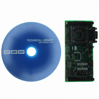
ATSTK501 Atmel, ATSTK501 Datasheet - Page 12

ATSTK501
Manufacturer Part Number
ATSTK501
Description
ADAPTER KIT FOR 64PIN AVR MCU
Manufacturer
Atmel
Datasheet
1.ATSTK501.pdf
(29 pages)
Specifications of ATSTK501
Accessory Type
STK500 Expansion Module
Processor To Be Evaluated
ATmega103 and ATmega128
Data Bus Width
8 bit
Interface Type
RS-232
For Use With/related Products
64-pin megaAVR Devices
For Use With
ATADAPCAN01 - EXTENSION CAN ADD-ON TO STK500/1ATSTK500 - PROGRAMMER AVR STARTER KIT
Lead Free Status / RoHS Status
Lead free / RoHS Compliant
Other names
Q1167170
STK501
STK501
STK501
STK501
Using the STK501 Top Module
2.5
2-6
External SRAM
Figure 2-8. Connecting JTAG ICE to the STK501
The STK501 contains a footprint where an external SRAM device can be mounted.
Make sure the SRAM device has the same voltage range as the rest of the design.
Caution: Special care should be taken if a low voltage SRAM is used, since High-volt-
age Programming requires a programming voltage higher than 4.5V. Low-voltage
SRAM may be damaged if High-voltage Programming of the target AVR is done.
Table 2-1 shows a list of recommended SRAM devices, and typical range of operation.
It is important that the SRAM device is soldered with the correct orientation as shown in
Figure 2-9.
Note:
Figure 2-9. Pin1 on SRAM Footprint and Pinout
The SRAM is disabled by default. To enable SRAM support, put a jumper
between the SRAMEN and GND pin on the PORTG/AUX connector.
AVR
GND
VCC
WE
CS
A0
A1
A2
A3
D0
D1
D2
D3
A4
A5
A6
A7
®
1
2
3
4
5
6
7
8
9
10
11
12
13
14
15
16
STK501 User Guide
128Kx8
32
31
30
29
28
27
26
25
24
23
22
21
20
19
18
17
A16
A15
A14
A13
OE
D7
D6
GND
VCC
D5
D4
A12
A11
A10
A9
A8


