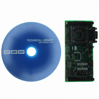
ATSTK501 Atmel, ATSTK501 Datasheet - Page 15

ATSTK501
Manufacturer Part Number
ATSTK501
Description
ADAPTER KIT FOR 64PIN AVR MCU
Manufacturer
Atmel
Datasheet
1.ATSTK501.pdf
(29 pages)
Specifications of ATSTK501
Accessory Type
STK500 Expansion Module
Processor To Be Evaluated
ATmega103 and ATmega128
Data Bus Width
8 bit
Interface Type
RS-232
For Use With/related Products
64-pin megaAVR Devices
For Use With
ATADAPCAN01 - EXTENSION CAN ADD-ON TO STK500/1ATSTK500 - PROGRAMMER AVR STARTER KIT
Lead Free Status / RoHS Status
Lead free / RoHS Compliant
Other names
Q1167170
STK501
STK501
STK501
STK501
2.9
2.10
AVR
®
STK501 User Guide
TOSC Switch
RS-232C Port
Figure 2-12. Enabling SRAM Interface for Devices in STK500
On the ATmega128(L) the TOSC1 and TOSC2 lines are shared with Port G (PG4 and
PG3). The TOSC switch select if the 32 kHz crystal, or the Port G connector pins should
be connected to the pins on the device.
Figure 2-13 shows a simplified block schematic on how this is implemented.
Note:
Figure 2-13. TOSC Block Schematic
The ATmega128(L) has an additional UART compared to the ATmega103(L). The RS-
232 port on the STK501 board has in addition to the RXD and TXD lines support for
RTS and CTS flow control. Figure 2-14 shows a simplified block schematic on how this
is implemented.
Note:
Port G is not available on the ATmega103(L), the switch will thus only select if
the 32 kHz crystal should be connected or not.
The UART in ATmega128(L) does not support hardware RTS or CTS control. If
such functionality is needed, it must be implemented in software.
PG3/TOSC2
PG4/TOSC1
AVR
TOSC
Switch
32 kHz
Using the STK501 Top Module
PG3
PG4
PORT G/AUX
Connector
To
2-9


