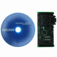
ATSTK501 Atmel, ATSTK501 Datasheet - Page 9

ATSTK501
Manufacturer Part Number
ATSTK501
Description
ADAPTER KIT FOR 64PIN AVR MCU
Manufacturer
Atmel
Datasheet
1.ATSTK501.pdf
(29 pages)
Specifications of ATSTK501
Accessory Type
STK500 Expansion Module
Processor To Be Evaluated
ATmega103 and ATmega128
Data Bus Width
8 bit
Interface Type
RS-232
For Use With/related Products
64-pin megaAVR Devices
For Use With
ATADAPCAN01 - EXTENSION CAN ADD-ON TO STK500/1ATSTK500 - PROGRAMMER AVR STARTER KIT
Lead Free Status / RoHS Status
Lead free / RoHS Compliant
Other names
Q1167170
STK501
STK501
STK501
STK501
2.2.2
2.2.2.1
2.2.2.2
2.2.2.3
2.2.2.4
2.3
2.3.1
AVR
®
STK501 User Guide
PORT G/AUX
PG0 - PG4
A16
SRAMEN
PEN
Programming the
ATmega103(L)/
128(L)
In-System
Programming
In addition to the normal Port G pins, this connector has some extra signals. See Figure
2-4.
Figure 2-4. PORTG/AUX
These are general I/O ports for the ATmega128(L) and connect to the ZIF socket and
the TQFP footprint. The PG3 and PG4 signals are routed through the TOSC switch
since these pins also are inputs for a 32 kHz oscillator. For a description on the TOSC
switch see Section 2.9.
Note:
This line goes to A16 (most significant address bit) on the SRAM. See Section 2.5 for
more information about this signal. can be connected to any AVR pin.
The SRAMEN signal controls if the SRAM is enabled or not. To enable the SRAM a
LOW level should be applied to this pin. See “External SRAM”, Section 2.5, for more
information on how to use this signal. This signal is pulled high by default.
The PEN pin is connected to the PEN pin on the ATmega103(L)/128(L). This pin is
described in the programming section of the ATmega103(L) and ATmega128(L)
datasheets.
The ATmega103(L) and ATmega128(L) can be programmed using both SPI and High-
voltage Parallel Programming. This sub section will explain how to connect the program-
ming cables to successfully use one of these two modes. The AVR Studio STK500
software is used in the same way as for other AVR parts.
Note:
To program the ATmega103(L) or ATmega128(L) using ISP programming mode, con-
nect the 6-wire cable between the ISP6PIN connector on the STK500 board and the ISP
connector on the STK501 board as shown in Figure 2-5.
The device can be programmed using the serial programming mode in the AVR Studio
STK500 software.
Note:
ATmega103(L) does not have Port G.
The ATmega128(L) also supports Self Programming. See AVR109 application
note for more information on this topic.
See the STK500 User Guide for information on how to use the STK500 front-
end software for ISP programming.
SRAMEN
GND
PG0
PG2
PG4
PORT G/AUX
1 2
PG1
PG3
A16
PEN
VTG
Using the STK501 Top Module
2-3


