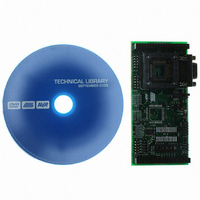
ATSTK501 Atmel, ATSTK501 Datasheet - Page 13

ATSTK501
Manufacturer Part Number
ATSTK501
Description
ADAPTER KIT FOR 64PIN AVR MCU
Manufacturer
Atmel
Datasheet
1.ATSTK501.pdf
(29 pages)
Specifications of ATSTK501
Accessory Type
STK500 Expansion Module
Processor To Be Evaluated
ATmega103 and ATmega128
Data Bus Width
8 bit
Interface Type
RS-232
For Use With/related Products
64-pin megaAVR Devices
For Use With
ATADAPCAN01 - EXTENSION CAN ADD-ON TO STK500/1ATSTK500 - PROGRAMMER AVR STARTER KIT
Lead Free Status / RoHS Status
Lead free / RoHS Compliant
Other names
Q1167170
STK501
STK501
STK501
STK501
2.5.1
2.5.2
AVR
®
STK501 User Guide
A16
SRAMEN
Table 2-1. Recommended SRAM Devices
The A16 pin on the PORTG/AUX connector is connected to A16 (address pin 16) on the
SRAM. ATmega103(L) and ATmega128(L) support up to 60 KB of external SRAM. The
STK501 SRAM footprint is for a 128 KB SRAM. Implementing software control of the
A16 line will increase the memory range from 64 KB to 128 KB. This line is pulled low by
default, addressing the lower 64 KB of the SRAM.
Figure 2-10. SRAM Block Schematic
The SRAMEN pin on the PORTG/AUX connector is connected to the Chip-enable (CE)
pin of the SRAM. This signal controls if the SRAM should be enabled or not. To enable
the SRAM, a low level should be applied to this pin. This pin is pulled high by default,
through a 10 k Ω resistor. Figure 2-10 shows a simplified block schematic on how the
SRAM interface is implemented. Figure 2-11 shows how to enable the SRAM by short-
ing SRAMEN and GND on the PORTG/AUX connector using one of the supplied
jumpers.
This signal can also be controlled by software or by some external control logic.
Manufacturer
ISSI
ISSI
ISSI
IDT
IDT
IDT
IDT
AVR
ALE (PG2)
WR (PG0)
RD (PG1)
PORTC
PORTA
PORTG/AUX
connector
From
SRAMEN
Part Number
IS63LV1024-T
IS63LV1024-J
IS63LV1024-K
IDT71124-Y
IDT71V124SA-TY
IDT71V124SA-Y
IDT71V124SA-PH
A16
PA7
PA6
PA5
PA4
PA3
PA2
PA1
PA0
LE
D7
D6
D5
D4
D3
D2
D1
D0
LATCH
PC7
PC6
PC5
PC4
PC3
PC2
PC1
PC0
OE
Q7
Q6
Q5
Q4
Q3
Q2
Q1
Q0
RAM HIGH
ADDRESS
A7
A6
A5
A4
A3
A2
A1
A0
10K x 12
VTG
A0
A2
A4
A6
Supply Voltage (V)
A[7:0]
Using the STK501 Top Module
3.3
3.3
3.3
5.0
3.3
3.3
3.3
A1
A3
A5
A7
VTG
A7
A6
A5
A4
A3
A2
A1
A0
A16
A15
A14
A13
A12
A11
A10
A9
A8
CE
OE
WE
A7
A6
A5
A4
A3
A2
A1
A0
TSOP-II
TSOP-II
Package
SOJ 300-mil
SOJ 400-mil
SOJ 400-mil
SOJ 300-mil
SOJ 400-mil
SRAM
D7
D6
D5
D4
D3
D2
D1
D0
PA7
PA6
PA5
PA4
PA3
PA2
PA1
PA0
2-7


