OM11024 NXP Semiconductors, OM11024 Datasheet - Page 17
OM11024
Manufacturer Part Number
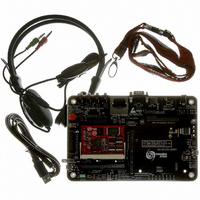
OM11024
Description
KIT EVAL FOR LPC313X
Manufacturer
NXP Semiconductors
Type
Microcontrollerr
Specifications of OM11024
Contents
2 Boards, cable and software
For Use With/related Products
LPC3131
Lead Free Status / RoHS Status
Lead free / RoHS Compliant
Other names
568-4719


NXP Semiconductors
LPC3130_3131
Preliminary data sheet
6.6 External Bus Interface (EBI)
6.7 Internal ROM Memory
The EBI module acts as multiplexer with arbitration between the NAND flash and the
SDRAM/SRAM memory modules connected externally through the MPMC.
The main purpose for using the EBI module is to save external pins. However only data
and address pins are multiplexed. Control signals towards and from the external memory
devices are not multiplexed.
Table 7.
The internal ROM memory is used to store the boot code of the LPC3130/3131. After a
reset, the ARM processor will start its code execution from this memory.
The LPC3130/3131 ROM memory has the following features:
The boot ROM determines the boot mode based on reset state of GPIO0, GPIO1, and
GPIO2 pins. To ensure that GPIO0, GPIO1 and GPIO2 pins come up as inputs, pins
TRST_N and JTAGSEL must be LOW during power-on reset (see UM10314 JTAG
chapter for details).
LPC3130/3131:
Module
External SRAM0
External SRAM1
External SDRAM0 0x3000 0000
•
•
•
•
•
•
•
•
•
•
•
– extended wait
One chip select for synchronous memory and two chip selects for static memory
devices.
Power-saving modes.
Dynamic memory self-refresh mode supported.
Controller support for 2 k, 4 k, and 8 k row address synchronous memory parts.
Support for all AHB burst types.
Little and big-endian support.
Support for the External Bus Interface (EBI) that enables the memory controller pads
to be shared.
Supports booting from SPI flash, NAND flash, SD/SDHC/MMC cards, UART, and
USB (DFU class) interfaces.
Supports option to perform CRC32 checking on the boot image.
Supports booting from managed NAND devices such as moviNAND, iNAND,
eMMC-NAND and eSD-NAND using SD/MMC boot mode.
Contains pre-defined MMU table (16 kB) for simple systems.
Memory map of the external SRAM/SDRAM memory modules
All information provided in this document is subject to legal disclaimers.
Maximum address space
0x2000 0000
0x2000 0000
0x2002 0000
0x2002 0000
Table 8
Rev. 1.04 — 27 May 2010
shows the various boot modes supported on the
Low-cost, low-power ARM926EJ-S microcontrollers
0x2000 FFFF
0x2001 FFFF
0x2002 FFFF
0x2003 FFFF
0x37FF FFFF
Data width
8 bit
16 bit
8 bit
16 bit
16 bit
LPC3130/3131
© NXP B.V. 2010. All rights reserved.
64 kB
128 kB
64 kB
128 kB
128 MB
Device size
17 of 72
Related parts for OM11024
Image
Part Number
Description
Manufacturer
Datasheet
Request
R

Part Number:
Description:
NXP Semiconductors designed the LPC2420/2460 microcontroller around a 16-bit/32-bitARM7TDMI-S CPU core with real-time debug interfaces that include both JTAG andembedded trace
Manufacturer:
NXP Semiconductors
Datasheet:

Part Number:
Description:
NXP Semiconductors designed the LPC2458 microcontroller around a 16-bit/32-bitARM7TDMI-S CPU core with real-time debug interfaces that include both JTAG andembedded trace
Manufacturer:
NXP Semiconductors
Datasheet:
Part Number:
Description:
NXP Semiconductors designed the LPC2468 microcontroller around a 16-bit/32-bitARM7TDMI-S CPU core with real-time debug interfaces that include both JTAG andembedded trace
Manufacturer:
NXP Semiconductors
Datasheet:
Part Number:
Description:
NXP Semiconductors designed the LPC2470 microcontroller, powered by theARM7TDMI-S core, to be a highly integrated microcontroller for a wide range ofapplications that require advanced communications and high quality graphic displays
Manufacturer:
NXP Semiconductors
Datasheet:
Part Number:
Description:
NXP Semiconductors designed the LPC2478 microcontroller, powered by theARM7TDMI-S core, to be a highly integrated microcontroller for a wide range ofapplications that require advanced communications and high quality graphic displays
Manufacturer:
NXP Semiconductors
Datasheet:
Part Number:
Description:
The Philips Semiconductors XA (eXtended Architecture) family of 16-bit single-chip microcontrollers is powerful enough to easily handle the requirements of high performance embedded applications, yet inexpensive enough to compete in the market for hi
Manufacturer:
NXP Semiconductors
Datasheet:
Part Number:
Description:
The XA-S3 device is a member of Philips Semiconductors? XA(eXtended Architecture) family of high performance 16-bitsingle-chip microcontrollers
Manufacturer:
NXP Semiconductors
Datasheet:

Part Number:
Description:
The NXP BlueStreak LH75401/LH75411 family consists of two low-cost 16/32-bit System-on-Chip (SoC) devices
Manufacturer:
NXP Semiconductors
Datasheet:
Part Number:
Description:
The NXP LPC3130/3131 combine an 180 MHz ARM926EJ-S CPU core, high-speed USB2
Manufacturer:
NXP Semiconductors
Datasheet:
Part Number:
Description:
The NXP LPC3141 combine a 270 MHz ARM926EJ-S CPU core, High-speed USB 2
Manufacturer:
NXP Semiconductors
Part Number:
Description:
The NXP LPC3143 combine a 270 MHz ARM926EJ-S CPU core, High-speed USB 2
Manufacturer:
NXP Semiconductors

Part Number:
Description:
The NXP LPC3152 combines an 180 MHz ARM926EJ-S CPU core, High-speed USB 2
Manufacturer:
NXP Semiconductors
Part Number:
Description:
The NXP LPC3154 combines an 180 MHz ARM926EJ-S CPU core, High-speed USB 2
Manufacturer:
NXP Semiconductors

Part Number:
Description:
Standard level N-channel enhancement mode Field-Effect Transistor (FET) in a plastic package using NXP High-Performance Automotive (HPA) TrenchMOS technology
Manufacturer:
NXP Semiconductors
Datasheet: