DEMO9S08QG8 Freescale Semiconductor, DEMO9S08QG8 Datasheet
DEMO9S08QG8
Specifications of DEMO9S08QG8
Available stocks


Related parts for DEMO9S08QG8


DEMO9S08QG8 Summary of contents
Page 1
... Freescale Semiconductor User Guide Application Module Student Learning Kit Users Guide featuring the Freescale MC9S08QG8 © Freescale Semiconductor, Inc., 2006. All rights reserved. _______________________________________________________________________ For use with the following part numbers: DEMO9S08QG8UG Rev. 0, 12/2006 APS08QG8SLK PBS08QG8SLK CSM9S08QG8SLK DEMO9S08QG8SLK ...
Page 2
... COMMUNICATIONS......................................................................................................................... 10 SCI PORT ........................................................................................................................................ 10 COM_EN ......................................................................................................................................... 10 COM CONNECTOR ........................................................................................................................ 11 SPI PORT......................................................................................................................................... 12 IIC PORT ......................................................................................................................................... 12 USER OPTIONS.................................................................................................................................. 12 PUSHBUTTON SWITCHES ............................................................................................................ 12 LED INDICATORS .......................................................................................................................... 12 POTENTIOMETER ......................................................................................................................... 12 PHOTOCELL................................................................................................................................... 12 I/O PORT CONNECTOR .................................................................................................................... 13 OPERATING MODES ........................................................................................................................ 14 RUN MODE..................................................................................................................................... 14 DEBUG MODE ............................................................................................................................... 14 DEVELOPMENT SUPPORT ................................................................................................................16 SOFTWARE DEVELOPMENT.......................................................................................................... 16 MEMORY MAP................................................................................................................................ 16 INTEGRATED BDM_PORT .............................................................................................................. 16 BDM_PORT HEADER ....................................................................................................................... 17 2 CONTENTS Freescale Semiconductor ...
Page 3
... Figure 4: COM Connector......................................................................................................................11 Figure 5: MCU I/O Port Connector .......................................................................................................13 Figure 6: BDM Port .................................................................................................................................17 Table 1: COM_EN Option Header........................................................................................................11 Table 2: User Option Jumper Settings.................................................................................................13 Table 3: Run Mode Setup ......................................................................................................................14 Table 4: Debug Mode Setup .................................................................................................................15 Table 5: Memory Map.............................................................................................................................16 Date December 14, 2005 Freescale Semiconductor FIGURES TABLES REVISION Rev 0 Initial Release. Comments 3 ...
Page 4
... Cut-Trace – a circuit trace connection between component pads. The circuit trace may be cut using a razor knife to break the default connection. To reconnect the circuit, simply install a suitably sized 0-ohm resistor or attach a wire across the pads. Throughout this document, where used, the name APS08QG8SLK applies equally to the APS08QG8SLK, CSM9S08QG8SLK, and PBS08QG8SLK. 4 Freescale Semiconductor ...
Page 5
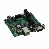
... FEATURES The APS08QG8SLK is an educational application module for the Freescale Semiconductor MC9S08QG8 microcontroller. Development of applications is quick and easy with the integrated USB-BDM, sample software tools, and examples. An optional BDM_PORT port is also provided to allow use of a BDM_PORT cable. A 32-pin connector allows connecting the APS08QG8SLK board to an expanded evaluation environment. • ...
Page 6
... Reference documents are provided on the support CD in Acrobat Reader format. More information can be found in the Application Notes section of the Freescale Web site. APS08QG8SLKUG.pdf HCS08QG8SCHEMSLKREVC.pdf APS08QG8SLK Board Schematic, Rev. C DEMO9S08QG8QSG.pdf DEMO9S08QG8TEST.zip DEMO9S08QG8_APP.pdf DEMO9S08QG8APP.zip AN2627.pdf Visit www.freescale.com\universityprogram and updates. 6 APS08QG8SLK User Guide (this document) ...
Page 7
... GETTING STARTED To get started quickly, please refer to the DEMO9S08QG8 Quick Start Guide included with the development kit. This quick start shows how to connect the board to the PC, run an LED test program, install the correct version of CodeWarrior Development Studio, and load an Analog to Digital (ATD) test program using CodeWarrior ...
Page 8
... Also, do not attempt to power the target board through this connector while also applying power through the USB-BDM or the PWR connector; damage to the board may result. 8 CONFIGURATION: Select power input from USB-BDM Select power input from VR1 Freescale Semiconductor ...
Page 9
... Device User Guide for more details on configuring the low power stop modes. TIMING By default, the APS08QG8SLK uses timing provided from an internal 32 kHz frequency reference and an internal frequency-locked loop (FLL). The FLL output is trimmable to ± 0.2% Freescale Semiconductor Enable power connection to connector J1 Disable power connection to connector J1 9 ...
Page 10
... COM_EN The COM_EN option header determines the operational status of the RS-232 transceiver. In the OFF position, the transceiver is disabled and all outputs are tri-stated. In the PTA4 position, the transceiver may be turned on or off using MCU GPIO signal PTA4. With the 10 Freescale Semiconductor ...
Page 11
... CTS GND 5 Freescale Semiconductor Female DB9 connector that interfaces to the HC(S)08 internal SCI1 serial port via the U2 RS232 transceiver. asynchronous serial communications without flow control. Flow control is provided at test points on the board. Pins 1, 4, and 6 are connected together. It provides simple 2-wire ...
Page 12
... A surface-mount phototransistor provides light sensitive, variable input for user applications. Current flow within the phototransistor is inversely proportional to light intensity incident on the surface of the device. A rail-to-rail OP amp at U2 boosts the photocell output to useable levels. This signal is available to the MCU on signal PTA1. Table 2 below details the user jumper settings. 12 Freescale Semiconductor ...
Page 13
... PTA3/KBI1P3/ADC1P3/SCL1 11 12 PTA5/ RESET*/IRQ*/TCLK 13 14 PTA0/KBI1P0/ADC1P0/TPM1CH0/AMCP PTB3/KBI1P7/ADC1P7/MOSI1 17 18 PTA1/KBI1P1/ADC1P1/ACMP1- PTB4/MISO1 19 20 PTA0/KBI1P0/ADC1P0/TPM1CH0/AMCP+ PTB2/KBI1P6/ADC1P6/SPSCK1 21 22 PTB5/TPM1CH1/SS1 23 24 PTA1/KBI1P1/ADC1P1/ACMP1 PTB6/SDA1/XTAL 27 28 PTB7/SCL1/EXTAL 29 30 PTA4/BKGD/MS/ACMP10 31 32 Freescale Semiconductor Off Disable SW1 Disable SW2 Disable LED1 Disable LED2 Disable RV1 Disable RZ1 VDD 1 2 ...
Page 14
... This header is not installed in default configurations. The steps below describe using the integrated USB-BDM. See the POWER section below for details on configuring the board for alternate power input. 1. Connect a serial cable (not included) between the board and a host PC if needed. 14 Freescale Semiconductor ...
Page 15
... Application development and debug for the target MC9S08QG8 is supported through the BDM interface. The debug interface consists of an integrated USB-BDM debugger and an optional 6-pin header (BDM_PORT). The BDM_PORT header is not installed in default configuration and may be installed by the user if needed. Freescale Semiconductor 15 ...
Page 16
... The integrated debugger provides power and ground to the target, thereby eliminating the need to power the board externally. When used, power from the USB-BDM circuit is derived 16 Direct Page Registers RAM Unimplemented High Page Registers Unimplemented FLASH Non-Volatile Registers Vectors 96 bytes 512 bytes 5,536 bytes 80 bytes 51,120 bytes 8192 bytes Freescale Semiconductor ...
Page 17
... Refer to the BDM cable documentation for details on the use of the BDM cable. The BDM_PORT header pin-out is shown below. Figure 6: BDM Port PTA4/ BKGD NOTE: This header is not installed in default configuration. Freescale Semiconductor GND See the HCS08 Device User Guide for 2 4 PTA5/RESET* complete BDM_PORT documentation 6 ...
Page 18
... Axiom Manufacturing 2813 Industrial Lane Garland, Tx. 75041 Phone: 972-926-9303 Web: www.axman.com Email: sales@axman.com DEMO9S08QG8UG Document Number: XX0000 Rev. 0 Rev. X 05/2006 09/2005 Information in this document is provided solely to enable system and software implementers to use Freescale Semiconductor products. There are no express or implied copyright licenses granted hereunder to design or fabricate any integrated circuits or integrated circuits based on the information in this document ...