DEMO9S08QG8 Freescale Semiconductor, DEMO9S08QG8 Datasheet - Page 7
DEMO9S08QG8
Manufacturer Part Number
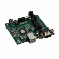
DEMO9S08QG8
Description
BOARD EVAL FOR MC9S08QG4/8
Manufacturer
Freescale Semiconductor
Datasheet
1.DEMO9S08QG8.pdf
(18 pages)
Specifications of DEMO9S08QG8
Lead Free Status / RoHS Status
Contains lead / RoHS non-compliant
Available stocks
Company
Part Number
Manufacturer
Quantity
Price
Company:

Part Number:
DEMO9S08QG8E
Manufacturer:
Freescale Semiconductor
Quantity:
135


INTRODUCTION
Before using this module, the user should be familiar with the hardware and software operation
of the target MCU. Refer to the MC9S08QG8 User Manual and MC9S08QG8 Reference
Manual for details on MCU operation. The module’s purpose is to promote the features of the
MC9S08QG8 and to assist the user in quickly developing an application in a known working
environment. Users should be familiar with memory mapping, memory types, and embedded
software design for quick, successful, application development.
The APS08QG8SLK application module is a fully assembled, fully functional module
supporting Freescale MC9S08QG8 microcontroller for educational use. The module comes
with a integrated USB Background Debug Mode (BDM), and USB cable for stand-alone
operation. Support software for this module is provided for Windows 95/98/NT/2000/XP
operating systems.
GETTING STARTED
To get started quickly, please refer to the DEMO9S08QG8 Quick Start Guide included with the
development kit. This quick start shows how to connect the board to the PC, run an LED test
program, install the correct version of CodeWarrior Development Studio, and load an Analog to
Digital (ATD) test program using CodeWarrior.
OPERATION
POWER
The APS08QG8SLK is designed to be powered from the USB_BDM during application
development. A 2.0mm barrel connector has been applied to support stand-alone operation.
In addition, the board may be powered through connector J1. The board may also be
configured to supply power through connector J1 to external circuitry.
When using the integrated USB-BDM, the board draws power from the USB bus. Total
current consumption of the board and connected circuitry, therefore, must be limited to less
than 500mA. Excessive current drain will violate the USB specification causing the USB bus
to disconnect. This will force a power-on-reset (POR).
CAUTION: Violating the USB specification will cause the USB bus to disconnect, forcing the
target to reset.
A 2.0mm barrel connector input has been provided to allow stand-alone operation. Voltage
input at this connector must be limited to between +5V and +18V. An LDO voltage regulator at
VR1 converts the input voltage to the +3.3V rail on the target board. VR1 will shut down if the
connected circuit draws excessive current. Stand-alone operation is also supported through
connector J1.
Freescale Semiconductor
7
Related parts for DEMO9S08QG8
Image
Part Number
Description
Manufacturer
Datasheet
Request
R

Part Number:
Description:
Manufacturer:
STMicroelectronics
Datasheet:

Part Number:
Description:
DEMO BOARD FOR HMC6042/HMC1041Z
Manufacturer:
Honeywell Microelectronics & Precision Sensors

Part Number:
Description:
DEMO BOARD FOR HMC1042L/HMC1041Z
Manufacturer:
Honeywell Microelectronics & Precision Sensors
Datasheet:

Part Number:
Description:
KIT DEMO 4 SENSOR CHAN RS232
Manufacturer:
VTI Technologies
Datasheet:


Part Number:
Description:
DEMO: DC Power Supply, 32 Volts, 3 Amps
Manufacturer:
Tektronix
Part Number:
Description:
DEMO: Programmable DC Power Supply, 32 Volts, 3 Amps
Manufacturer:
Tektronix

Part Number:
Description:
Manufacturer:
Freescale Semiconductor, Inc
Datasheet:
Part Number:
Description:
Manufacturer:
Freescale Semiconductor, Inc
Datasheet:
Part Number:
Description:
Manufacturer:
Freescale Semiconductor, Inc
Datasheet:
Part Number:
Description:
Manufacturer:
Freescale Semiconductor, Inc
Datasheet:
Part Number:
Description:
Manufacturer:
Freescale Semiconductor, Inc
Datasheet:
Part Number:
Description:
Manufacturer:
Freescale Semiconductor, Inc
Datasheet:
Part Number:
Description:
Manufacturer:
Freescale Semiconductor, Inc
Datasheet:
Part Number:
Description:
Manufacturer:
Freescale Semiconductor, Inc
Datasheet: