DEMO9S08QG8 Freescale Semiconductor, DEMO9S08QG8 Datasheet - Page 12
DEMO9S08QG8
Manufacturer Part Number
DEMO9S08QG8
Description
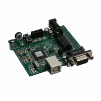
BOARD EVAL FOR MC9S08QG4/8
Manufacturer
Freescale Semiconductor
Datasheet
1.DEMO9S08QG8.pdf
(18 pages)
Specifications of DEMO9S08QG8
Lead Free Status / RoHS Status
Contains lead / RoHS non-compliant
Available stocks
Company
Part Number
Manufacturer
Quantity
Price
Company:

Part Number:
DEMO9S08QG8E
Manufacturer:
Freescale Semiconductor
Quantity:
135


SPI Port
SPI signaling connects directly between connector J1 and the MCU. Refer to the
MC9S08QG8 Device User Guide for details on using the SPI interface.
IIC Port
IIC signaling connects directly between connector J1 and the MCU. Refer to the MC9S08QG8
Device User Guide for details on using the IIC interface.
USER OPTIONS
The APS08QG8SLK includes various input and output devices to aid application development.
User I/O devices include 2 momentary pushbutton switches, 2 green LEDs, 1 potentiometer,
and 1 phototransistor. Each device may be enabled or disabled individually by the USER_EN
option header. Each user enable is clearly marked as to functionality.
Pushbutton Switches
Two push button switches provide momentary, active-low input, for user applications. Pull-ups
internal to the MCU must be enabled to provide error free switch operation. Pushbutton
switches SW1 and SW2 are enabled to the MCU I/O ports by the USER option bank. SW1
and SW2 connect to input ports PTA2 and PTA3 respectively. Table 2 below details the user
jumper settings.
LED Indicators
Indicators LED1 and LED2 are enabled from HC(S)08 I/O ports by the USER option bank.
Each LED is active-low and illuminates when a logic low signal is driven from the respective
MCU I/O port. MCU ports PTB6 and PTB7 drive LED1 and LED2 respectively. Table 2 below
details the user jumper settings.
Potentiometer
A 5k ohm, thumb-wheel type, potentiometer at RV1 provides variable resistance input for user
applications. The output is the result of a voltage divider that changes as the thumb-wheel is
turned. The potentiometer is connected between VDD and GND with the center tap providing
the divider output. This center tap is connected to the MCU on signal PTA0. Table 2 below
details the user jumper settings.
Photocell
A surface-mount phototransistor provides light sensitive, variable input for user applications.
Current flow within the phototransistor is inversely proportional to light intensity incident on the
surface of the device. A rail-to-rail OP amp at U2 boosts the photocell output to useable
levels. This signal is available to the MCU on signal PTA1. Table 2 below details the user
jumper settings.
12
Freescale Semiconductor
Related parts for DEMO9S08QG8
Image
Part Number
Description
Manufacturer
Datasheet
Request
R

Part Number:
Description:
Manufacturer:
STMicroelectronics
Datasheet:

Part Number:
Description:
DEMO BOARD FOR HMC6042/HMC1041Z
Manufacturer:
Honeywell Microelectronics & Precision Sensors

Part Number:
Description:
DEMO BOARD FOR HMC1042L/HMC1041Z
Manufacturer:
Honeywell Microelectronics & Precision Sensors
Datasheet:

Part Number:
Description:
KIT DEMO 4 SENSOR CHAN RS232
Manufacturer:
VTI Technologies
Datasheet:


Part Number:
Description:
DEMO: DC Power Supply, 32 Volts, 3 Amps
Manufacturer:
Tektronix
Part Number:
Description:
DEMO: Programmable DC Power Supply, 32 Volts, 3 Amps
Manufacturer:
Tektronix

Part Number:
Description:
Manufacturer:
Freescale Semiconductor, Inc
Datasheet:
Part Number:
Description:
Manufacturer:
Freescale Semiconductor, Inc
Datasheet:
Part Number:
Description:
Manufacturer:
Freescale Semiconductor, Inc
Datasheet:
Part Number:
Description:
Manufacturer:
Freescale Semiconductor, Inc
Datasheet:
Part Number:
Description:
Manufacturer:
Freescale Semiconductor, Inc
Datasheet:
Part Number:
Description:
Manufacturer:
Freescale Semiconductor, Inc
Datasheet:
Part Number:
Description:
Manufacturer:
Freescale Semiconductor, Inc
Datasheet:
Part Number:
Description:
Manufacturer:
Freescale Semiconductor, Inc
Datasheet: