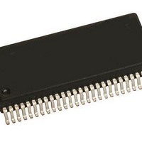
KIT33927EKEVBE Freescale Semiconductor, KIT33927EKEVBE Datasheet - Page 12

KIT33927EKEVBE
Manufacturer Part Number
KIT33927EKEVBE
Description
KIT EVALUATION FOR MC33927
Manufacturer
Freescale Semiconductor
Series
SMARTMOS™r
Type
Other Power Managementr
Datasheet
1.KIT33927EKEVBE.pdf
(44 pages)
Specifications of KIT33927EKEVBE
Main Purpose
Power Management, FET Driver (External FET)
Embedded
No
Utilized Ic / Part
MC33927
Primary Attributes
*
Secondary Attributes
8 V ~ 40 V Supply
Interface Type
SPI
Product
Power Management Modules
Silicon Manufacturer
Freescale
Silicon Core Number
MC33927
Kit Application Type
Power Management
Application Sub Type
FET Driver
Kit Contents
Board, CD
Rohs Compliant
Yes
Lead Free Status / RoHS Status
Lead free / RoHS Compliant
For Use With/related Products
MC33927
Table 3. Static Electrical Characteristics (continued)
values noted reflect the approximate parameter means at T
12
33927
ELECTRICAL CHARACTERISTICS
STATIC ELECTRICAL CHARACTERISTICS
SUPERVISORY AND CONTROL CIRCUITS
THERMAL WARNING
Notes
Logic Inputs (Px_LS, Px_HS, EN1, EN2)
Logic Inputs (SI, SCLK,
Input Logic Threshold Hysteresis
Input Pull-Down Current, (Px_LS, SI, SCLK, EN1, EN2)
Input Pull-Up Current, (CS, Px_HS)
Input Capacitance
RST Threshold
RST Pull-Down Resistance
Power-ON RST Threshold, (V
SO High-Level Output Voltage
SO Low-Level Output Voltage
SO Tri-State Leakage Current
SO Tri-State Capacitance
INT High-Level Output Voltage
INT Low-Level Output Voltage
Thermal Warning Temperature
Thermal Hysteresis
26.
27.
28.
29.
30.
31.
Characteristics noted under conditions 8.0V ≤ V
High-Level Input Voltage Threshold
Low-Level Input Voltage Threshold
High-Level Input Voltage Threshold
Low-Level Input Voltage Threshold
Inputs Px_LS, SI, SCLK,
0.3 V
0 ≤ V
0.0 ≤ V
0.3 V
I
I
CS = 0.7 V
0.0 ≤ V
I
I
OH
OL
OH
OL
This parameter is guaranteed by design, not production tested.
Logic threshold voltages derived relative to a 3.3V 10% system.
Pull-Up circuits will not allow back biasing of V
There are two elements in the RST circuit: 1) one generally lower threshold enables the internal regulator; 2) the second removes the
reset from the internal logic.
This parameter applies to the OFF state (tri-stated) condition of SO is guaranteed by design but is not production tested.
The Thermal Warning circuit does not force IC shutdown above this temperature. It is possible to set a bit in the MASK register to
generate an interrupt when overtemperature is detected, and the status bits will always read back the state of the three individual
Thermal Warning circuits in the IC.
= 1.0mA
= 500µA
= 1.0mA
= -500µA
DD
IN
DD
IN
IN
≤ 0.7 V
≤ V
≤ V
≤ 5.5V
≤ 5.5V
DD
IN
IN
(29)
, 0.3 V
≤ V
≤ V
DD
(26)
(26)
DD
DD
DD
CS
= V
(26)
)
Characteristic
CS
(26)
,
DD
SO
(30)
, Px_HS, EN1, EN2
(26)
,
(27)
Falling)
= 0.7 V
(26)
,
(28)
(31)
DD
(27)
DD.
PWR
= V
BAT
A
= 25°C under nominal conditions unless otherwise noted.
≤ 40V, -40°C ≤ T
I
SO_LEAK_T
V
Symbol
V
T
C
T
V
TH_RST
R
V
I
I
V
THRST
V
V
WARN
INPD
INPU
V
V
C
HYST
V
V
SO_T
IHYS
SOH
SOL
RST
OH
OL
IH
IL
IH
IL
IN
A
≤ 125°C, unless otherwise noted. Typical
0.85 V
0.9 V
Min
100
-1.0
150
0.9
0.9
8.0
1.0
3.4
10
40
–
–
–
–
–
–
8
DD
DD
Analog Integrated Circuit Device Data
Typ
250
170
4.0
15
60
15
10
–
–
–
–
–
–
–
–
–
–
–
–
Freescale Semiconductor
0.1 V
Max
V
450
185
2.1
2.1
2.1
4.5
1.0
0.5
18
25
85
12
–
–
–
–
–
DD
DD
% VDD
Unit
mV
µA
µA
pF
kΩ
µA
pF
°C
°C
V
V
V
V
V
V
V


