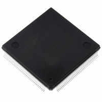
ST10R167-Q3 STMicroelectronics, ST10R167-Q3 Datasheet - Page 14

ST10R167-Q3
Manufacturer Part Number
ST10R167-Q3
Description
IC MCU 16BIT ROMLESS 144-PQFP
Manufacturer
STMicroelectronics
Series
ST10r
Datasheet
1.ST10R167-Q3.pdf
(63 pages)
Specifications of ST10R167-Q3
Core Processor
ST10
Core Size
16-Bit
Speed
25MHz
Connectivity
CAN, EBI/EMI, SSC, UART/USART
Peripherals
POR, PWM, WDT
Number Of I /o
111
Program Memory Type
ROMless
Ram Size
4K x 8
Voltage - Supply (vcc/vdd)
4.5 V ~ 5.5 V
Data Converters
A/D 16x10b
Oscillator Type
Internal
Operating Temperature
-40°C ~ 125°C
Package / Case
144-QFP
Processor Series
ST10R1x
Core
ST10
Data Bus Width
16 bit
Program Memory Size
32 KB
Data Ram Size
4 KB
Interface Type
CAN/SSC/USART
Maximum Clock Frequency
25 MHz
Number Of Programmable I/os
111
Number Of Timers
5
Maximum Operating Temperature
+ 125 C
Mounting Style
SMD/SMT
Minimum Operating Temperature
- 40 C
On-chip Adc
16-ch x 10-bit
Lead Free Status / RoHS Status
Lead free / RoHS Compliant
Eeprom Size
-
Program Memory Size
-
Lead Free Status / Rohs Status
Lead free / RoHS Compliant
Other names
497-2043
Available stocks
Company
Part Number
Manufacturer
Quantity
Price
Company:
Part Number:
ST10R167-Q3
Manufacturer:
ST
Quantity:
556
Company:
Part Number:
ST10R167-Q3
Manufacturer:
STMicroelectronics
Quantity:
10 000
Part Number:
ST10R167-Q3
Manufacturer:
ST
Quantity:
20 000
Company:
Part Number:
ST10R167-Q3/TR
Manufacturer:
STMicroelectronics
Quantity:
10 000
Company:
Part Number:
ST10R167-Q3B0
Manufacturer:
ST
Quantity:
1 343
Part Number:
ST10R167-Q3B0
Manufacturer:
ST
Quantity:
20 000
ST10R167
VII - INTERRUPT SYSTEM
The interrupt response time for internal program
execution is from 200ns to 480ns.
The ST10R167 architecture supports several
mechanisms for fast and flexible response to ser-
vice requests that can be generated from various
sources internal or external to the microcontroller.
Any of these interrupt requests can be serviced by
the Interrupt Controller or by the Peripheral Event
Controller (PEC).
In contrast to a standard interrupt service where
the current program execution is suspended and
a branch to the interrupt vector table is performed,
just one cycle is ‘stolen’ from the current CPU
activity to perform a PEC service. A PEC service
implies a single Byte or Word data transfer
between any two memory locations with an addi-
tional increment of either the PEC source or the
destination pointer. An individual PEC transfer
counter is implicitly decremented for each PEC
service except when performing in the continuous
transfer mode. When this counter reaches zero, a
standard interrupt is performed to the correspond-
ing source related vector location. PEC services
are very well suited, for example, for supporting
the transmission or reception of blocks of data.
The ST10R167 has 8 PEC channels each of
Table 2 : Interrupt sources
14/63
CAPCOM Register 0
CAPCOM Register 1
CAPCOM Register 2
CAPCOM Register 3
CAPCOM Register 4
CAPCOM Register 5
CAPCOM Register 6
CAPCOM Register 7
CAPCOM Register 8
CAPCOM Register 9
CAPCOM Register 10
CAPCOM Register 11
CAPCOM Register 12
CAPCOM Register 13
CAPCOM Register 14
CAPCOM Register 15
CAPCOM Register 16
CAPCOM Register 17
Source of Interrupt or PEC
Service Request
Request
CC10IR
CC11IR
CC12IR
CC13IR
CC14IR
CC15IR
CC16IR
CC17IR
CC0IR
CC1IR
CC2IR
CC3IR
CC4IR
CC5IR
CC6IR
CC7IR
CC8IR
CC9IR
Flag
CC10IE
CC12IE
CC13IE
CC14IE
CC15IE
CC16IE
CC17IE
CC11IE
Enable
CC0IE
CC1IE
CC2IE
CC3IE
CC4IE
CC5IE
CC6IE
CC7IE
CC8IE
CC9IE
Flag
which offers such fast interrupt-driven data trans-
fer capabilities.
A interrupt control register which contains an
interrupt request flag, an interrupt enable flag and
an interrupt priority bitfield is dedicated to each
existing interrupt source. Thanks to its related
register, each source can be programmed to one
of sixteen interrupt priority levels. Once starting to
be processed by the CPU, an interrupt service
can only be interrupted by a higher prioritized
service request. For the standard interrupt
processing, each of the possible interrupt sources
has a dedicated vector location.
Fast external interrupt inputs are provided to ser-
vice external interrupts with high precision
requirements. These fast interrupt inputs feature
programmable edge detection (rising edge, falling
edge or both edges).
Software interrupts are supported by means of the
‘TRAP’ instruction in combination with an individ-
ual trap (interrupt) number.
Table 2 shows all the available ST10R167 inter-
rupt sources and the corresponding hard-
ware-related
locations and trap (interrupt) numbers :
CC10INT
CC12INT
CC13INT
CC14INT
CC15INT
CC16INT
CC17INT
Interrupt
CC11INT
CC0INT
CC1INT
CC2INT
CC3INT
CC4INT
CC5INT
CC6INT
CC7INT
CC8INT
CC9INT
Vector
interrupt
00’004Ch
00’005Ch
00’006Ch
00’007Ch
00’00C0h
00’00C4h
Location
00’0040h
00’0044h
00’0048h
00’0050h
00’0054h
00’0058h
00’0060h
00’0064h
00’0068h
00’0070h
00’0074h
00’0078h
Vector
flags, vectors, vector
Number
Trap
1Ah
1Bh
1Ch
1Dh
1Eh
10h
12h
13h
14h
15h
16h
17h
18h
19h
1Fh
30h
31h
11h


