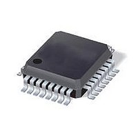
ST7FLI49MK1T6 STMicroelectronics, ST7FLI49MK1T6 Datasheet - Page 132

ST7FLI49MK1T6
Manufacturer Part Number
ST7FLI49MK1T6
Description
MCU 8BIT SGL VOLT FLASH 32-LQFP
Manufacturer
STMicroelectronics
Series
ST7r
Datasheet
1.ST7FLI49MK1T6TR.pdf
(187 pages)
Specifications of ST7FLI49MK1T6
Core Processor
ST7
Core Size
8-Bit
Speed
8MHz
Connectivity
I²C
Peripherals
LVD, POR, PWM, WDT
Number Of I /o
24
Program Memory Size
4KB (4K x 8)
Program Memory Type
FLASH
Eeprom Size
128 x 8
Ram Size
384 x 8
Voltage - Supply (vcc/vdd)
2.4 V ~ 5.5 V
Data Converters
A/D 10x10b
Oscillator Type
Internal
Operating Temperature
-40°C ~ 85°C
Package / Case
32-LQFP
Processor Series
ST7FLI4x
Core
ST7
Data Bus Width
8 bit
Data Ram Size
384 B
Interface Type
I2C
Maximum Clock Frequency
8 MHz
Number Of Programmable I/os
24
Number Of Timers
5
Maximum Operating Temperature
+ 125 C
Mounting Style
SMD/SMT
Minimum Operating Temperature
- 40 C
On-chip Adc
10 bit, 10 Channel
Lead Free Status / RoHS Status
Lead free / RoHS Compliant
Available stocks
Company
Part Number
Manufacturer
Quantity
Price
Company:
Part Number:
ST7FLI49MK1T6
Manufacturer:
st
Quantity:
456
Company:
Part Number:
ST7FLI49MK1T6
Manufacturer:
STMicroelectronics
Quantity:
10 000
Part Number:
ST7FLI49MK1T6
Manufacturer:
ST
Quantity:
20 000
Company:
Part Number:
ST7FLI49MK1T6TR
Manufacturer:
STMicroelectronics
Quantity:
10 000
Instruction set
12.1.2
12.1.3
12.1.4
132/188
Table 52.
Immediate mode
Immediate instructions have 2 bytes, the first byte contains the opcode, the second byte
contains the operand value.
Table 53.
Direct modes
In Direct instructions, the operands are referenced by their memory address.
The direct addressing mode consists of two submodes:
Direct (short) addressing mode
The address is a byte, thus requires only 1 byte after the opcode, but only allows 00 - FF
addressing space.
Direct (long) addressing mode
The address is a word, thus allowing 64 Kbyte addressing space, but requires 2 bytes after
the opcode.
Indexed modes (no offset, short, long)
In this mode, the operand is referenced by its memory address, which is defined by the
unsigned addition of an index register (X or Y) with an offset.
The indirect addressing mode consists of three submodes:
Indexed mode (no offset)
There is no offset (no extra byte after the opcode), and allows 00 - FF addressing space.
Indexed mode (short)
The offset is a byte, thus requires only 1 byte after the opcode and allows 00 - 1FE
addressing space.
Imm
SLL, SRL, SRA, RLC, RRC
Immediate instruction
ADC, ADD, SUB, SBC
Instructions supporting inherent addressing mode (continued)
Instructions supporting inherent immediate addressing mode
AND, OR, XOR
Instruction
BCP
SWAP
CP
LD
MUL
Doc ID 13562 Rev 3
Shift and rotate operations
Arithmetic operations
Logical operations
Byte multiplication
Bit compare
Swap nibbles
Function
Compare
Function
Load
ST7LITE49M


