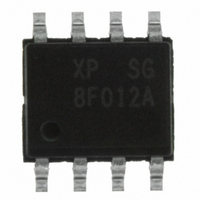
Z8F012ASB020SG Zilog, Z8F012ASB020SG Datasheet - Page 117

Z8F012ASB020SG
Manufacturer Part Number
Z8F012ASB020SG
Description
IC ENCORE XP MCU FLASH 1K 8SOIC
Manufacturer
Zilog
Series
Encore!® XP®r
Datasheet
1.Z8F011ASB020EG.pdf
(282 pages)
Specifications of Z8F012ASB020SG
Core Processor
Z8
Core Size
8-Bit
Speed
20MHz
Connectivity
IrDA, UART/USART
Peripherals
Brown-out Detect/Reset, LED, LVD, POR, PWM, Temp Sensor, WDT
Number Of I /o
6
Program Memory Size
1KB (1K x 8)
Program Memory Type
FLASH
Eeprom Size
16 x 8
Ram Size
256 x 8
Voltage - Supply (vcc/vdd)
2.7 V ~ 3.6 V
Data Converters
A/D 4x10b
Oscillator Type
Internal
Operating Temperature
0°C ~ 70°C
Package / Case
8-SOIC (3.9mm Width)
Processor Series
Z8F012Ax
Core
eZ8
Data Bus Width
8 bit
Data Ram Size
256 B
Interface Type
UART
Maximum Clock Frequency
20 MHz
Number Of Programmable I/os
6
Number Of Timers
2
Operating Supply Voltage
2.7 V to 3.6 V
Maximum Operating Temperature
+ 70 C
Mounting Style
SMD/SMT
Development Tools By Supplier
Z8F04A08100KITG, Z8F04A28100KITG, ZENETSC0100ZACG, ZENETSC0100ZACG, ZUSBOPTSC01ZACG, ZUSBSC00100ZAC, ZUSBSC00100ZACG
Minimum Operating Temperature
0 C
On-chip Adc
10 bit, 4 Channel
Lead Free Status / RoHS Status
Lead free / RoHS Compliant
Other names
269-4039
Z8F012ASB020SG
Z8F012ASB020SG
- Current page: 117 of 282
- Download datasheet (4Mb)
PS022825-0908
Note:
send. This action provides 7 bit periods of latency to load the Transmit Data register
before the Transmit shift register completes shifting the current character. Writing to the
UART Transmit Data register clears the TDRE bit to 0.
Receiver Interrupts
The receiver generates an interrupt when any of the following occurs:
UART Overrun Errors
When an overrun error condition occurs the UART prevents overwriting of the valid data
currently in the Receive Data register. The Break Detect and Overrun status bits are not
displayed until after the valid data has been read.
After the valid data has been read, the UART Status 0 register is updated to indicate the
overrun condition (and Break Detect, if applicable). The RDA bit is set to 1 to indicate that
the Receive Data register contains a data byte. However, because the overrun error
occurred, this byte may not contain valid data and must be ignored. The BRKD bit indi-
cates if the overrun was caused by a break condition on the line. After reading the status
byte indicating an overrun error, the Receive Data register must be read again to clear the
error bits is the UART Status 0 register. Updates to the Receive Data register occur only
when the next data word is received.
UART Data and Error Handling Procedure
Figure 15
service routines.
•
•
•
•
A data byte is received and is available in the UART Receive Data register. This
interrupt can be disabled independently of the other receiver interrupt sources. The
received data interrupt occurs after the receive character has been received and placed
in the Receive Data register. To avoid an overrun error, software must respond to this
received data available condition before the next character is completely received.
In MULTIPROCESSOR mode (
dent on the multiprocessor configuration and the most recent address byte.
A break is received.
An overrun is detected.
A data framing error is detected.
displays the recommended procedure for use in UART receiver interrupt
MPEN =
1), the receive data interrupts are depen-
Universal Asynchronous Receiver/Transmitter
Z8 Encore! XP
Product Specification
®
F082A Series
106
Related parts for Z8F012ASB020SG
Image
Part Number
Description
Manufacturer
Datasheet
Request
R

Part Number:
Description:
Communication Controllers, ZILOG INTELLIGENT PERIPHERAL CONTROLLER (ZIP)
Manufacturer:
Zilog, Inc.
Datasheet:

Part Number:
Description:
KIT DEV FOR Z8 ENCORE 16K TO 64K
Manufacturer:
Zilog
Datasheet:

Part Number:
Description:
KIT DEV Z8 ENCORE XP 28-PIN
Manufacturer:
Zilog
Datasheet:

Part Number:
Description:
DEV KIT FOR Z8 ENCORE 8K/4K
Manufacturer:
Zilog
Datasheet:

Part Number:
Description:
KIT DEV Z8 ENCORE XP 28-PIN
Manufacturer:
Zilog
Datasheet:

Part Number:
Description:
DEV KIT FOR Z8 ENCORE 4K TO 8K
Manufacturer:
Zilog
Datasheet:

Part Number:
Description:
CMOS Z8 microcontroller. ROM 16 Kbytes, RAM 256 bytes, speed 16 MHz, 32 lines I/O, 3.0V to 5.5V
Manufacturer:
Zilog, Inc.
Datasheet:

Part Number:
Description:
Low-cost microcontroller. 512 bytes ROM, 61 bytes RAM, 8 MHz
Manufacturer:
Zilog, Inc.
Datasheet:

Part Number:
Description:
Z8 4K OTP Microcontroller
Manufacturer:
Zilog, Inc.
Datasheet:

Part Number:
Description:
CMOS SUPER8 ROMLESS MCU
Manufacturer:
Zilog, Inc.
Datasheet:

Part Number:
Description:
SL1866 CMOSZ8 OTP Microcontroller
Manufacturer:
Zilog, Inc.
Datasheet:

Part Number:
Description:
SL1866 CMOSZ8 OTP Microcontroller
Manufacturer:
Zilog, Inc.
Datasheet:

Part Number:
Description:
OTP (KB) = 1, RAM = 125, Speed = 12, I/O = 14, 8-bit Timers = 2, Comm Interfaces Other Features = Por, LV Protect, Voltage = 4.5-5.5V
Manufacturer:
Zilog, Inc.
Datasheet:

Part Number:
Description:
Manufacturer:
Zilog, Inc.
Datasheet:


