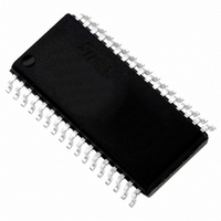
ST72F621L4M1 STMicroelectronics, ST72F621L4M1 Datasheet - Page 135

ST72F621L4M1
Manufacturer Part Number
ST72F621L4M1
Description
IC MCU 8BIT LS 16K 34-SOIC
Manufacturer
STMicroelectronics
Series
ST7r
Datasheet
1.ST72F622L2M1.pdf
(139 pages)
Specifications of ST72F621L4M1
Core Processor
ST7
Core Size
8-Bit
Speed
8MHz
Connectivity
SCI, SPI, USB
Peripherals
DMA, LVD, POR, PWM, WDT
Number Of I /o
23
Program Memory Size
16KB (16K x 8)
Program Memory Type
FLASH
Ram Size
768 x 8
Voltage - Supply (vcc/vdd)
4 V ~ 5.5 V
Data Converters
A/D 8x10b
Oscillator Type
Internal
Operating Temperature
0°C ~ 70°C
Package / Case
34-SOIC (7.5mm Width)
Processor Series
ST72F6x
Core
ST7
Data Bus Width
8 bit
Data Ram Size
768 B
Interface Type
SCI, SPI, USB
Maximum Clock Frequency
12 MHz
Number Of Programmable I/os
23
Number Of Timers
2
Operating Supply Voltage
4 V to 5.5 V
Maximum Operating Temperature
+ 70 C
Mounting Style
SMD/SMT
Minimum Operating Temperature
0 C
On-chip Adc
10 bit
For Use With
497-5046 - KIT TOOL FOR ST7/UPSD/STR7 MCU
Lead Free Status / RoHS Status
Lead free / RoHS Compliant
Eeprom Size
-
Lead Free Status / Rohs Status
In Transition
Other names
497-2112-5
Available stocks
Company
Part Number
Manufacturer
Quantity
Price
Company:
Part Number:
ST72F621L4M1
Manufacturer:
ST
Quantity:
2 272
Company:
Part Number:
ST72F621L4M1
Manufacturer:
ST
Quantity:
5
15 IMPORTANT NOTES
Refer to
codes for each of the recent silicon revisions.
Silicon revisions are identifiable:
– on the device package, by the last letter of the
– on the box, by the last 3 digits of the Internal
See also
15.1 A/ D CONVERTER ACCURACY FOR FIRST
CONVERSION
Description
When the ADC is enabled after being powered
down (for example when waking up from HALT,
ACTIVE-HALT or setting the ADON bit in the AD-
CCSR register), the first conversion (8-bit or 10-
bit) accuracy does not meet the accuracy specified
in the datasheet.
Workaround
In order to have the accuracy specified in the
datasheet, the first conversion after a ADC switch-
on has to be ignored.
Note:
This limitation does not apply to Flash silicon rev.
G devices (see
15.2 A/D CONVERTER CONVERSION SPEED
Description
Following a change in the fabrication location, the
typical ADC conversion speed value for Flash de-
vices has improved from a previous value of 28µs
to 4µs.
Trace Code marked on the device package.
Sales Type printed in the box label.
Table 32
Figure 92. on page 137
Table
which provides a list of the trace
32).
Doc ID 6996 Rev 5
Table 32. Device Identification
When migrating software from Rev X to Rev G de-
vices (refer to
when using ADC interrupts.
Workaround
Firstly, on Rev G devices, only the use of One-
Shot conversion mode is recommended in con-
nection with ADC interrupts.
In Continuous Conversion mode, to avoid getting
trapped in a continuous interrupt, the ADC inter-
rupt routine must always have sufficient time to ex-
ecute completely before the next ADC conversion
interrupt, especially if the ADC interrupt is disabled
outside of this routine. With the shorter conversion
speed value, the interrupt may not be serviced fast
enough. For this reason, on Rev G devices, the
Continuous Conversion mode is not recommend-
ed in connection with ADC interrupts.
Secondly, in the interests of keeping code portable
between all Flash/ROM versions, using the ADC
as a source of a delayed trigger event is not ad-
vised. However, in such a scenario, a delay loop
should be inserted for Rev G Flash devices to en-
sure that the timing remains the same for any such
ADC delayed trigger events.
Flash Devices (Rev G)
(Latest Flash silicon)
Flash Devices (Rev X)
(Previous Flash silicon)
ROM Devices (Rev Z)
(Silicon Rev.)
Device Type
Table
Trace Code marked on device/
Internal Sales Type on box
label
“xxxxxxxxxG” / 72F62xxxxx$x4
“xxxxxxxxxX” / 72F62xxxxx$x8
“xxxxxxxxxX” / 72F62xxxxx$x9
“xxxxxxxxxZ” / 7262xxxxx$x2
“xxxxxxxxxZ” / 7262xxxxx$x3
32) care should be taken
135/139


