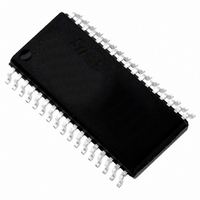
ST72F621L4M1 STMicroelectronics, ST72F621L4M1 Datasheet - Page 31

ST72F621L4M1
Manufacturer Part Number
ST72F621L4M1
Description
IC MCU 8BIT LS 16K 34-SOIC
Manufacturer
STMicroelectronics
Series
ST7r
Datasheet
1.ST72F622L2M1.pdf
(139 pages)
Specifications of ST72F621L4M1
Core Processor
ST7
Core Size
8-Bit
Speed
8MHz
Connectivity
SCI, SPI, USB
Peripherals
DMA, LVD, POR, PWM, WDT
Number Of I /o
23
Program Memory Size
16KB (16K x 8)
Program Memory Type
FLASH
Ram Size
768 x 8
Voltage - Supply (vcc/vdd)
4 V ~ 5.5 V
Data Converters
A/D 8x10b
Oscillator Type
Internal
Operating Temperature
0°C ~ 70°C
Package / Case
34-SOIC (7.5mm Width)
Processor Series
ST72F6x
Core
ST7
Data Bus Width
8 bit
Data Ram Size
768 B
Interface Type
SCI, SPI, USB
Maximum Clock Frequency
12 MHz
Number Of Programmable I/os
23
Number Of Timers
2
Operating Supply Voltage
4 V to 5.5 V
Maximum Operating Temperature
+ 70 C
Mounting Style
SMD/SMT
Minimum Operating Temperature
0 C
On-chip Adc
10 bit
For Use With
497-5046 - KIT TOOL FOR ST7/UPSD/STR7 MCU
Lead Free Status / RoHS Status
Lead free / RoHS Compliant
Eeprom Size
-
Lead Free Status / Rohs Status
In Transition
Other names
497-2112-5
Available stocks
Company
Part Number
Manufacturer
Quantity
Price
Company:
Part Number:
ST72F621L4M1
Manufacturer:
ST
Quantity:
2 272
Company:
Part Number:
ST72F621L4M1
Manufacturer:
ST
Quantity:
5
POWER SAVING MODES (Cont’d)
8.3 HALT MODE
The HALT mode is the MCU lowest power con-
sumption mode. The HALT mode is entered by ex-
ecuting the HALT instruction. The internal oscilla-
tor is then turned off, causing all internal process-
ing to be stopped, including the operation of the
on-chip peripherals.
When entering HALT mode, the I bit in the Condi-
tion Code Register is cleared. Thus, any of the ex-
ternal interrupts (ITi or USB end suspend mode),
are allowed and if an interrupt occurs, the CPU
clock becomes active.
The MCU can exit HALT mode on reception of ei-
ther an external interrupt on ITi, an end suspend
mode interrupt coming from USB peripheral, or a
reset. The oscillator is then turned on and a stabi-
lization time is provided before releasing CPU op-
eration. The stabilization time is 514 CPU clock cy-
cles.
After the start up delay, the CPU continues opera-
tion by servicing the interrupt which wakes it up or
by fetching the reset vector if a reset wakes it up.
Doc ID 6996 Rev 5
Figure 25. HALT Mode Flow Chart
Note: Before servicing an interrupt, the CC register is
pushed on the stack. The I-Bit is set during the inter-
rupt routine and cleared when the CC register is
popped.
N
INTERRUPT*
EXTERNAL
Y
OSCILLATOR
PERIPH. CLOCK
CPU CLOCK
I-BIT
OSCILLATOR
PERIPH. CLOCK
CPU CLOCK
OR SERVICE INTERRUPT
I-BIT
FETCH RESET VECTOR
N
514 CPU CLOCK
CYCLES DELAY
HALT INSTRUCTION
RESET
Y
ST7262xxx
OFF
OFF
OFF
CLEARED
ON
ON
ON
SET
31/139


