ST72F621L4M1 STMicroelectronics, ST72F621L4M1 Datasheet - Page 85
ST72F621L4M1
Manufacturer Part Number
ST72F621L4M1
Description
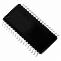
IC MCU 8BIT LS 16K 34-SOIC
Manufacturer
STMicroelectronics
Series
ST7r
Datasheet
1.ST72F622L2M1.pdf
(139 pages)
Specifications of ST72F621L4M1
Core Processor
ST7
Core Size
8-Bit
Speed
8MHz
Connectivity
SCI, SPI, USB
Peripherals
DMA, LVD, POR, PWM, WDT
Number Of I /o
23
Program Memory Size
16KB (16K x 8)
Program Memory Type
FLASH
Ram Size
768 x 8
Voltage - Supply (vcc/vdd)
4 V ~ 5.5 V
Data Converters
A/D 8x10b
Oscillator Type
Internal
Operating Temperature
0°C ~ 70°C
Package / Case
34-SOIC (7.5mm Width)
Processor Series
ST72F6x
Core
ST7
Data Bus Width
8 bit
Data Ram Size
768 B
Interface Type
SCI, SPI, USB
Maximum Clock Frequency
12 MHz
Number Of Programmable I/os
23
Number Of Timers
2
Operating Supply Voltage
4 V to 5.5 V
Maximum Operating Temperature
+ 70 C
Mounting Style
SMD/SMT
Minimum Operating Temperature
0 C
On-chip Adc
10 bit
For Use With
497-5046 - KIT TOOL FOR ST7/UPSD/STR7 MCU
Lead Free Status / RoHS Status
Lead free / RoHS Compliant
Eeprom Size
-
Lead Free Status / Rohs Status
In Transition
Other names
497-2112-5
Available stocks
Company
Part Number
Manufacturer
Quantity
Price
Company:

Part Number:
ST72F621L4M1
Manufacturer:
ST
Quantity:
2 272
Company:
Part Number:
ST72F621L4M1
Manufacturer:
ST
Quantity:
5


USB INTERFACE (Cont’d)
PID REGISTER (PIDR)
Read only
Reset Value: xx00 0000 (x0h)
Bits 7:6 = TP[3:2] Token PID bits 3 & 2.
USB token PIDs are encoded in four bits. TP[3:2]
correspond to the variable token PID bits 3 & 2.
Note: PID bits 1 & 0 have a fixed value of 01.
When a CTR interrupt occurs (see register ISTR)
the software should read the TP3 and TP2 bits to
retrieve the PID name of the token received.
The USB standard defines TP bits as:
Bits 5:3 Reserved. Forced by hardware to 0.
Bit 2 = RX_SEZ Received single-ended zero
This bit indicates the status of the RX_SEZ trans-
ceiver output.
0: No SE0 (single-ended zero) state
1: USB lines are in SE0 (single-ended zero) state
Bit 1 = RXD Received data
0: No K-state
1: USB lines are in K-state
This bit indicates the status of the RXD transceiver
output (differential receiver output).
Note: If the environment is noisy, the RX_SEZ and
RXD bits can be used to secure the application. By
interpreting the status, software can distinguish a
valid End Suspend event from a spurious wake-up
due to noise on the external USB line. A valid End
Suspend is followed by a Resume or Reset se-
quence. A Resume is indicated by RXD=1, a Re-
set is indicated by RX_SEZ=1.
Bit 0 = Reserved. Forced by hardware to 0.
TP3
7
TP3
0
1
1
TP2
0
TP2
0
0
1
0
0
RX_
SEZ
PID Name
SETUP
OUT
IN
RXD
0
0
Doc ID 6996 Rev 5
INTERRUPT STATUS REGISTER (ISTR)
Read / Write
Reset Value: 0000 0000 (00h)
When an interrupt occurs these bits are set by
hardware. Software must read them to determine
the interrupt type and clear them after servicing.
Note: These bits cannot be set by software.
Bit 7 = SUSP Suspend mode request.
This bit is set by hardware when a constant idle
state is present on the bus line for more than 3 ms,
indicating a suspend mode request from the USB
bus. The suspend request check is active immedi-
ately after each USB reset event and its disabled
by hardware when suspend mode is forced
(FSUSP bit of CTLR register) until the end of
resume sequence.
Bit 6 = DOVR DMA over/underrun.
This bit is set by hardware if the ST7 processor
can’t answer a DMA request in time.
0: No over/underrun detected
1: Over/underrun detected
Bit 5 = CTR Correct Transfer. This bit is set by
hardware when a correct transfer operation is per-
formed. The type of transfer can be determined by
looking at bits TP3-TP2 in register PIDR. The End-
point on which the transfer was made is identified
by bits EP1-EP0 in register IDR.
0: No Correct Transfer detected
1: Correct Transfer detected
Note: A transfer where the device sent a NAK or
STALL handshake is considered not correct (the
host only sends ACK handshakes). A transfer is
considered correct if there are no errors in the PID
and CRC fields, if the DATA0/DATA1 PID is sent
as expected, if there were no data overruns, bit
stuffing or framing errors.
Bit 4 = ERR Error.
This bit is set by hardware whenever one of the er-
rors listed below has occurred:
0: No error detected
1: Timeout, CRC, bit stuffing or nonstandard
SUSP
framing error detected
7
DOVR
CTR
ERR
IOVR
ESUSP
ST7262xxx
RESET
85/139
SOF
0
Related parts for ST72F621L4M1
Image
Part Number
Description
Manufacturer
Datasheet
Request
R

Part Number:
Description:
STMicroelectronics [RIPPLE-CARRY BINARY COUNTER/DIVIDERS]
Manufacturer:
STMicroelectronics
Datasheet:
Part Number:
Description:
STMicroelectronics [LIQUID-CRYSTAL DISPLAY DRIVERS]
Manufacturer:
STMicroelectronics
Datasheet:

Part Number:
Description:
BOARD EVAL FOR MEMS SENSORS
Manufacturer:
STMicroelectronics
Datasheet:
Part Number:
Description:
NPN TRANSISTOR POWER MODULE
Manufacturer:
STMicroelectronics
Datasheet:
Part Number:
Description:
TURBOSWITCH ULTRA-FAST HIGH VOLTAGE DIODE
Manufacturer:
STMicroelectronics
Datasheet:
Part Number:
Description:
Manufacturer:
STMicroelectronics
Datasheet:
Part Number:
Description:
DIODE / SCR MODULE
Manufacturer:
STMicroelectronics
Datasheet:
Part Number:
Description:
DIODE / SCR MODULE
Manufacturer:
STMicroelectronics
Datasheet:
Part Number:
Description:
Search -----> STE16N100
Manufacturer:
STMicroelectronics
Datasheet:
Part Number:
Description:
Search ---> STE53NA50
Manufacturer:
STMicroelectronics
Datasheet:
Part Number:
Description:
NPN Transistor Power Module
Manufacturer:
STMicroelectronics
Datasheet:
Part Number:
Description:
DIODE / SCR MODULE
Manufacturer:
STMicroelectronics
Datasheet: