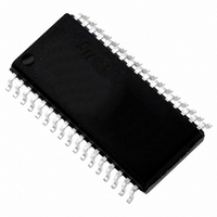
ST72F621L4M1 STMicroelectronics, ST72F621L4M1 Datasheet - Page 93

ST72F621L4M1
Manufacturer Part Number
ST72F621L4M1
Description
IC MCU 8BIT LS 16K 34-SOIC
Manufacturer
STMicroelectronics
Series
ST7r
Datasheet
1.ST72F622L2M1.pdf
(139 pages)
Specifications of ST72F621L4M1
Core Processor
ST7
Core Size
8-Bit
Speed
8MHz
Connectivity
SCI, SPI, USB
Peripherals
DMA, LVD, POR, PWM, WDT
Number Of I /o
23
Program Memory Size
16KB (16K x 8)
Program Memory Type
FLASH
Ram Size
768 x 8
Voltage - Supply (vcc/vdd)
4 V ~ 5.5 V
Data Converters
A/D 8x10b
Oscillator Type
Internal
Operating Temperature
0°C ~ 70°C
Package / Case
34-SOIC (7.5mm Width)
Processor Series
ST72F6x
Core
ST7
Data Bus Width
8 bit
Data Ram Size
768 B
Interface Type
SCI, SPI, USB
Maximum Clock Frequency
12 MHz
Number Of Programmable I/os
23
Number Of Timers
2
Operating Supply Voltage
4 V to 5.5 V
Maximum Operating Temperature
+ 70 C
Mounting Style
SMD/SMT
Minimum Operating Temperature
0 C
On-chip Adc
10 bit
For Use With
497-5046 - KIT TOOL FOR ST7/UPSD/STR7 MCU
Lead Free Status / RoHS Status
Lead free / RoHS Compliant
Eeprom Size
-
Lead Free Status / Rohs Status
In Transition
Other names
497-2112-5
Available stocks
Company
Part Number
Manufacturer
Quantity
Price
Company:
Part Number:
ST72F621L4M1
Manufacturer:
ST
Quantity:
2 272
Company:
Part Number:
ST72F621L4M1
Manufacturer:
ST
Quantity:
5
10-BIT A/D CONVERTER (ADC) (Cont’d)
To read only 8 bits, perform the following steps:
1. Wait for interrupt or poll the EOC bit
2. Read ADCDRMSB
The EOC bit is reset by hardware once the AD-
CDRMSB is read.
To start another conversion, user should set the
ADON bit once again.
ADC Continuous Conversion mode
In the ADCCSR register:
1.Reset the ONE SHOT bit to put the A/D con-
2.Set the ADON bit to enable the A/D converter
Note: Changing the A/D channel during conver-
sion will stop the current conversion and start con-
version of the newly selected channel.
When a conversion is complete:
To read the 10 bits, perform the following steps:
1. Wait for interrupt or poll the EOC bit
2. Read ADCDRLSB
3. Read ADCDRMSB
The EOC bit is reset by hardware once the AD-
CDRMSB is read.
To read only 8 bits, perform the following steps:
1. Wait for interrupt
2. Read ADCDRMSB
The EOC bit is reset by hardware once the AD-
CDRMSB is read.
Changing the conversion channel
The application can change channels during con-
version. In this case the current conversion is
stopped and the A/D converter starts converting
the newly selected channel.
verter in continuous mode.
and to start the first conversion. From this time
on, the ADC performs a continuous conversion
of the selected channel.
– The EOC bit is set by hardware.
– An interrupt request is generated if the ITE bit
– The result is in the ADCDR registers and re-
is set.
mains valid until the next conversion has end-
ed.
Doc ID 6996 Rev 5
ADCCR consistency
If an End Of Conversion event occurs after soft-
ware has read the ADCDRLSB but before it has
read the ADCDRMSB, there would be a risk that
the two values read would belong to different sam-
ples.
To guarantee consistency:
Thus, it is mandatory to read the ADCDRMSB just
after reading the ADCDRLSB. This is especially
important in continuous mode, as the ADCDR reg-
ister will not be updated until the ADCDRMSB is
read.
10.7.4 Low Power Modes
Note: The A/D converter may be disabled by re-
setting the ADON bit. This feature allows reduced
power consumption when no conversion is need-
ed and between single shot conversions.
10.7.5 Interrupts
Note: The EOC interrupt event is connected to an
interrupt vector (see Interrupts chapter).
It generates an interrupt if the ITE bit is set in the
ADCCSR register and the interrupt mask in the CC
register is reset (RIM instruction).
Mode
WAIT
HALT
End of Conversion
– The ADCDRMSB and the ADCDRLSB are
– The ADCDRMSB and the ADCDRLSB are un-
Interrupt Event
locked when the ADCCRLSB is read
locked when the MSB is read or when ADON
is reset.
Description
No effect on A/D Converter
A/D Converter disabled.
After wakeup from Halt mode, the A/D
Converter requires a stabilisation time
t
before accurate conversions can be
performed.
STAB
(see Electrical Characteristics)
Event
EOC
Flag
Control
Enable
ITE
Bit
from
Wait
Exit
Yes
from
93/139
Halt
Exit
No


