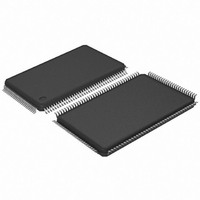
AT91SAM7SE512-AU Atmel, AT91SAM7SE512-AU Datasheet - Page 13

AT91SAM7SE512-AU
Manufacturer Part Number
AT91SAM7SE512-AU
Description
IC ARM7 MCU FLASH 512K 128-LQFP
Manufacturer
Atmel
Series
AT91SAMr
Specifications of AT91SAM7SE512-AU
Core Processor
ARM7
Core Size
16/32-Bit
Speed
55MHz
Connectivity
EBI/EMI, I²C, SPI, SSC, UART/USART, USB
Peripherals
Brown-out Detect/Reset, POR, PWM, WDT
Number Of I /o
88
Program Memory Size
512KB (512K x 8)
Program Memory Type
FLASH
Ram Size
32K x 8
Voltage - Supply (vcc/vdd)
1.65 V ~ 1.95 V
Data Converters
A/D 8x10b
Oscillator Type
Internal
Operating Temperature
-40°C ~ 85°C
Package / Case
128-LQFP
Cpu Family
91S
Device Core
ARM7TDMI
Device Core Size
32b
Frequency (max)
55MHz
Interface Type
EBI/SPI/TWI/USART
Total Internal Ram Size
32KB
# I/os (max)
88
Number Of Timers - General Purpose
3
Operating Supply Voltage (typ)
1.8/3.3V
Operating Supply Voltage (max)
1.95/3.6V
Operating Supply Voltage (min)
1.65/3V
On-chip Adc
8-chx10-bit
Instruction Set Architecture
RISC
Operating Temp Range
-40C to 85C
Operating Temperature Classification
Industrial
Mounting
Surface Mount
Pin Count
128
Package Type
LQFP
No. Of I/o's
88
Ram Memory Size
32KB
Cpu Speed
48MHz
No. Of Timers
3
No. Of Pwm Channels
4
Digital Ic Case Style
LQFP
Rohs Compliant
Yes
Processor Series
AT91SAMx
Core
ARM7TDMI
Data Bus Width
32 bit
Data Ram Size
32 KB
Maximum Clock Frequency
48 MHz
Number Of Programmable I/os
32
Number Of Timers
3
Operating Supply Voltage
1.8 V to 3.3 V
Maximum Operating Temperature
+ 85 C
Mounting Style
SMD/SMT
3rd Party Development Tools
JTRACE-ARM-2M, KSK-AT91SAM7S-PL, MDK-ARM, RL-ARM, ULINK2
Development Tools By Supplier
AT91SAM-ICE, AT91-ISP, AT91SAM7SE-EK
Minimum Operating Temperature
- 40 C
For Use With
AT91SAM7SE-EK - EVAL BOARD FOR AT91SAM7SEAT91SAM-ICE - EMULATOR FOR AT91 ARM7/ARM9
Lead Free Status / RoHS Status
Lead free / RoHS Compliant
Eeprom Size
-
Lead Free Status / Rohs Status
Compliant
Available stocks
Company
Part Number
Manufacturer
Quantity
Price
Company:
Part Number:
AT91SAM7SE512-AU
Manufacturer:
AMTEL
Quantity:
382
Part Number:
AT91SAM7SE512-AU
Manufacturer:
ATMEL/爱特梅尔
Quantity:
20 000
- Current page: 13 of 673
- Download datasheet (11Mb)
5. Power Considerations
5.1
5.2
5.3
6222F–ATARM–14-Jan-11
Power Supplies
Power Consumption
Voltage Regulator
The SAM7SE512/256/32 has six types of power supply pins and integrates a voltage regulator,
allowing the device to be supplied with only one voltage. The six power supply pin types are:
In order to decrease current consumption, if the voltage regulator and the ADC are not used,
VDDIN, ADVREF, AD4, AD5, AD6 and AD7 should be connected to GND. In this case VDDOUT
should be left unconnected.
No separate ground pins are provided for the different power supplies. Only GND pins are pro-
vided and should be connected as shortly as possible to the system ground plane.
The SAM7SE512/256/32 has a static current of less than 60 µA on VDDCORE at 25°C, includ-
ing the RC oscillator, the voltage regulator and the power-on reset when the brownout detector
is deactivated. Activating the brownout detector adds 20 µA static current.
The dynamic power consumption on VDDCORE is less than 80 mA at full speed when running
out of the Flash. Under the same conditions, the power consumption on VDDFLASH does not
exceed 10 mA.
The SAM7SE512/256/32 embeds a voltage regulator that is managed by the System Controller.
In Normal Mode, the voltage regulator consumes less than 100 µA static current and draws 100
mA of output current.
The voltage regulator also has a Low-power Mode. In this mode, it consumes less than 20 µA
static current and draws 1 mA of output current.
Adequate output supply decoupling is mandatory for VDDOUT to reduce ripple and avoid oscil-
lations. The best way to achieve this is to use two capacitors in parallel:
• VDDIN pin. It powers the voltage regulator and the ADC; voltage ranges from 3.0V to 3.6V,
• VDDOUT pin. It is the output of the 1.8V voltage regulator.
• VDDIO pin. It powers the I/O lines; two voltage ranges are supported:
• VDDFLASH pin. It powers the USB transceivers and a part of the Flash. It is required for the
• VDDCORE pins. They power the logic of the device; voltage ranges from 1.65V to 1.95V,
• VDDPLL pin. It powers the oscillator and the PLL. It can be connected directly to the
• One external 470 pF (or 1 nF) NPO capacitor should be connected between VDDOUT and
3.3V nominal.
Flash to operate correctly; voltage ranges from 3.0V to 3.6V, 3.3V nominal.
1.8V typical. It can be connected to the VDDOUT pin with decoupling capacitor. VDDCORE
is required for the device, including its embedded Flash, to operate correctly.
VDDOUT pin.
GND as close to the chip as possible.
– from 3.0V to 3.6V, 3.3V nominal
– or from 1.65V to 1.95V, 1.8V nominal.
SAM7SE512/256/32 Preliminary
13
Related parts for AT91SAM7SE512-AU
Image
Part Number
Description
Manufacturer
Datasheet
Request
R

Part Number:
Description:
EVAL BOARD FOR AT91SAM7SE
Manufacturer:
Atmel
Datasheet:

Part Number:
Description:
KIT EVAL FOR ARM AT91SAM7S
Manufacturer:
Atmel
Datasheet:

Part Number:
Description:
MCU, MPU & DSP Development Tools KICKSTART KIT ATMEL AT91SAM7S
Manufacturer:
IAR Systems

Part Number:
Description:
MCU ARM9 64K SRAM 144-LFBGA
Manufacturer:
Atmel
Datasheet:

Part Number:
Description:
IC ARM7 MCU FLASH 256K 100LQFP
Manufacturer:
Atmel
Datasheet:

Part Number:
Description:
IC ARM9 MPU 217-LFBGA
Manufacturer:
Atmel
Datasheet:

Part Number:
Description:
MCU ARM9 ULTRA LOW PWR 217-LFBGA
Manufacturer:
Atmel
Datasheet:

Part Number:
Description:
MCU ARM9 324-TFBGA
Manufacturer:
Atmel
Datasheet:

Part Number:
Description:
IC MCU ARM9 SAMPLING 217CBGA
Manufacturer:
Atmel
Datasheet:

Part Number:
Description:
IC ARM9 MCU 217-LFBGA
Manufacturer:
Atmel
Datasheet:

Part Number:
Description:
IC ARM9 MCU 208-PQFP
Manufacturer:
Atmel
Datasheet:

Part Number:
Description:
MCU ARM 512K HS FLASH 100-LQFP
Manufacturer:
Atmel
Datasheet:

Part Number:
Description:
MCU ARM 512K HS FLASH 100-TFBGA
Manufacturer:
Atmel
Datasheet:

Part Number:
Description:
IC ARM9 MCU 200 MHZ 324-TFBGA
Manufacturer:
Atmel
Datasheet:

Part Number:
Description:
IC ARM MCU 16BIT 128K 256BGA
Manufacturer:
Atmel
Datasheet:


