ETRX3DVKA357 Telegesis Ltd, ETRX3DVKA357 Datasheet - Page 11
ETRX3DVKA357
Manufacturer Part Number
ETRX3DVKA357
Description
KIT DEVELOPMENT FOR ETRX357
Manufacturer
Telegesis Ltd
Type
ZigBit™r
Specifications of ETRX3DVKA357
Frequency
2.4GHz
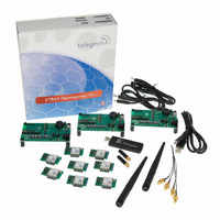
Kit Contents
3x ETRX35xDV Development Boards, 3x USB Cables, 2x ETRX35x On Carrier Boards, 2x ETRX35xHR Boards
Mcu Supported Families
ETRX3
Silicon Manufacturer
Telegesis
Rohs Compliant
Yes
Lead Free Status / RoHS Status
Lead free / RoHS Compliant
For Use With/related Products
ETRX357
Lead Free Status / RoHS Status
Lead free / RoHS Compliant, Lead free / RoHS Compliant
Other names
920-1009
ETRX2DVK357
ETRX2DVK357


Power supply jumpers: links must be inserted at JP3 and JP6 according to the DC supply feed.
JP3 can be left connected at all time, but it disconnects the serial interface lines and prevents
power drain through them when the serial (USB) interface is not used. This will minimise the
current drain from a battery and produce a more accurate reading of the current consumption.
It permissible to attach a USB connection while the board is powered from a battery or external
supply.
There are three options:
Insert JP3. Connect the centre
pin of JP6 to ‘Ext’.
Instead of a shorting link, a current meter can be inserted at JP6 to monitor the power
consumption.
9.2 Development Board Sensors
The board’s temperature sensor is a National Semiconductor LM61 which has an offset of 600mV
and a sensitivity of 10mV/deg. Hence for example 0°C give 600mV and 20° gives 800mV.
The light sensor is an Avago APDS 9005; it indicates ambient light level but is not suitable for
accurate measurements.
©2010 Telegesis (UK) Ltd
USB power
Optionally, omit JP3. Connect the
centre pin of JP6 to ‘Ext’.
External power through the X2
Figure 7. Power feed options
socket
- 11 -
ETRX35xDVK Product Manual (Rev 1.01)
Optionally, omit JP3. Connect the
centre pin of JP6 to ‘Batt’.
ETRX35x Development Kit
Battery power
Related parts for ETRX3DVKA357
Image
Part Number
Description
Manufacturer
Datasheet
Request
R

Part Number:
Description:
MODULE ZIGBEE USB STICK
Manufacturer:
Telegesis Ltd
Datasheet:

Part Number:
Description:
MODULE ZIGBEE PWR AMP USB STICK
Manufacturer:
Telegesis Ltd
Datasheet:

Part Number:
Description:
ZIGBEE ETHERNET ACCESS POINT
Manufacturer:
Telegesis Ltd
Datasheet:

Part Number:
Description:
ZIGBEE ETHERNET ACCESS POINT
Manufacturer:
Telegesis Ltd
Datasheet:

Part Number:
Description:
MODULE ZIGBEE EM357 W/CHIP ANT
Manufacturer:
Telegesis Ltd
Datasheet:

Part Number:
Description:
MODULE ZIGBEE EM250 CHIP ANT
Manufacturer:
Telegesis Ltd
Datasheet:

Part Number:
Description:
MODULE ZIGBEE W/PWR AMP
Manufacturer:
Telegesis Ltd
Datasheet:
Part Number:
Description:
MODULE ZIGBEE W/PA LNA CHIP ANT
Manufacturer:
Telegesis Ltd
Datasheet:
Part Number:
Description:
MODULE ZIGBEE W/PA LNA U.FL
Manufacturer:
Telegesis Ltd
Datasheet:
Part Number:
Description:
MODULE, ZIGBEE, ETRX351, CHIP ANT
Manufacturer:
Telegesis Ltd
Datasheet:
Part Number:
Description:
MODULE, ZIGBEE, ETRX3, HIROSE
Manufacturer:
Telegesis Ltd
Datasheet:
Part Number:
Description:
MODULE, ZIGBEE, ETRX3, PA+LNA, CHIP
Manufacturer:
Telegesis Ltd
Datasheet:
Part Number:
Description:
MODULE, ZIGBEE, ETRX3, PA+LNA, HIROS
Manufacturer:
Telegesis Ltd
Datasheet:
Part Number:
Description:
MODULE, ZIGBEE, ETRX351, HIROSE
Manufacturer:
Telegesis Ltd
Datasheet:
Part Number:
Description:
MODULE
Manufacturer:
Telegesis Ltd
Datasheet: