ETRX3DVKA357 Telegesis Ltd, ETRX3DVKA357 Datasheet - Page 9
ETRX3DVKA357
Manufacturer Part Number
ETRX3DVKA357
Description
KIT DEVELOPMENT FOR ETRX357
Manufacturer
Telegesis Ltd
Type
ZigBit™r
Specifications of ETRX3DVKA357
Frequency
2.4GHz
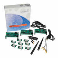
Kit Contents
3x ETRX35xDV Development Boards, 3x USB Cables, 2x ETRX35x On Carrier Boards, 2x ETRX35xHR Boards
Mcu Supported Families
ETRX3
Silicon Manufacturer
Telegesis
Rohs Compliant
Yes
Lead Free Status / RoHS Status
Lead free / RoHS Compliant
For Use With/related Products
ETRX357
Lead Free Status / RoHS Status
Lead free / RoHS Compliant, Lead free / RoHS Compliant
Other names
920-1009
ETRX2DVK357
ETRX2DVK357


ETRX35x Development Kit
9 The Development Board
9.1 Development Board Interface Description
Figure 4. The development board
Figure 4 shows the location of the connectors described below.
Programming Connector:
The 10-way programming connector X3 is used to program the
ETRX35x module from an Ember InSight Adaptor. It is duplicated on the carrier board, and will not
normally be fitted in the Development Board.
USB Port:
The USB serial port allows connectivity to a PC.
This provides access to the
command line interface and the bootloader for firmware upgrades, and supplies DC power to the
board.
I/O connection: JP1 and JP2 can be used to connect the I/O pins as shown in Table 4.
Reference Ground: JP4 is connected to the devboard’s ground plane. It can be used as a
reference point when making measurements on the devboard.
©2010 Telegesis (UK) Ltd
- 9 -
ETRX35xDVK Product Manual (Rev 1.01)
Related parts for ETRX3DVKA357
Image
Part Number
Description
Manufacturer
Datasheet
Request
R

Part Number:
Description:
MODULE ZIGBEE USB STICK
Manufacturer:
Telegesis Ltd
Datasheet:

Part Number:
Description:
MODULE ZIGBEE PWR AMP USB STICK
Manufacturer:
Telegesis Ltd
Datasheet:

Part Number:
Description:
ZIGBEE ETHERNET ACCESS POINT
Manufacturer:
Telegesis Ltd
Datasheet:

Part Number:
Description:
ZIGBEE ETHERNET ACCESS POINT
Manufacturer:
Telegesis Ltd
Datasheet:

Part Number:
Description:
MODULE ZIGBEE EM357 W/CHIP ANT
Manufacturer:
Telegesis Ltd
Datasheet:

Part Number:
Description:
MODULE ZIGBEE EM250 CHIP ANT
Manufacturer:
Telegesis Ltd
Datasheet:

Part Number:
Description:
MODULE ZIGBEE W/PWR AMP
Manufacturer:
Telegesis Ltd
Datasheet:
Part Number:
Description:
MODULE ZIGBEE W/PA LNA CHIP ANT
Manufacturer:
Telegesis Ltd
Datasheet:
Part Number:
Description:
MODULE ZIGBEE W/PA LNA U.FL
Manufacturer:
Telegesis Ltd
Datasheet:
Part Number:
Description:
MODULE, ZIGBEE, ETRX351, CHIP ANT
Manufacturer:
Telegesis Ltd
Datasheet:
Part Number:
Description:
MODULE, ZIGBEE, ETRX3, HIROSE
Manufacturer:
Telegesis Ltd
Datasheet:
Part Number:
Description:
MODULE, ZIGBEE, ETRX3, PA+LNA, CHIP
Manufacturer:
Telegesis Ltd
Datasheet:
Part Number:
Description:
MODULE, ZIGBEE, ETRX3, PA+LNA, HIROS
Manufacturer:
Telegesis Ltd
Datasheet:
Part Number:
Description:
MODULE, ZIGBEE, ETRX351, HIROSE
Manufacturer:
Telegesis Ltd
Datasheet:
Part Number:
Description:
MODULE
Manufacturer:
Telegesis Ltd
Datasheet: