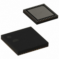
EM250-RTR Ember, EM250-RTR Datasheet - Page 25

EM250-RTR
Manufacturer Part Number
EM250-RTR
Description
IC ZIGBEE SYSTEM-ON-CHIP 48-QFN
Manufacturer
Ember
Series
EM250r
Datasheet
1.EM250-JMP-R.pdf
(117 pages)
Specifications of EM250-RTR
Frequency
2.4GHz
Modulation Or Protocol
802.15.4 Zigbee
Applications
Home/Building Automation, Industrial Control and Monitoring
Power - Output
3dBm
Sensitivity
-97dBm
Voltage - Supply
2 V ~ 3.6 V
Current - Receiving
35.5mA
Current - Transmitting
33mA
Data Interface
PCB, Surface Mount
Memory Size
128kB Flash, 5kB SRAM
Antenna Connector
PCB, Surface Mount
Operating Temperature
-40°C ~ 85°C
Package / Case
48-QFN
For Use With
636-1009 - PROGRAMMER USB FLASH EM250/260
Lead Free Status / RoHS Status
Lead free / RoHS Compliant
Data Rate - Maximum
-
Other names
636-1000-2
Available stocks
Company
Part Number
Manufacturer
Quantity
Price
Company:
Part Number:
EM250-RTR
Manufacturer:
TI
Quantity:
3 400
Part Number:
EM250-RTR
Manufacturer:
EMBER
Quantity:
20 000
4.11 Random Number Generator
4.12 Watchdog Timer
4.13 Sleep Timer
Timekeeping accuracy depends on temperature fluctuations the chip is exposed to, power supply impedance,
and the calibration interval, but in general it will be better than 150ppm (including crystal error of 40ppm).
Table 14 lists the specifications of the RC oscillator.
Parameter
Frequency
Analog trim steps
Frequency variation with supply
The EM250 allows for the generation of random numbers by exposing a randomly generated bit from the RX
ADC. Analog noise current is passed through the RX path, sampled by the receive ADC, and stored in a regis-
ter. The value contained in this register could be used to seed a software-generated random number. The Em-
berZNet stack utilizes these random numbers to seed the Random MAC Backoff and Encryption Key Genera-
tors.
The EM250 contains a watchdog timer clocked from the internal oscillator. The watchdog is disabled by de-
fault, but can be enabled or disabled by software.
If the timer reaches its time-out value of approximately 2 seconds, it will generate a reset signal to the chip.
When software is running properly, the application can periodically restart this timer to prevent the reset sig-
nal from being generated.
The watchdog will generate a low watermark interrupt in advance of actually resetting the chip. This low wa-
termark interrupt occurs approximately 1.75 seconds after the timer has been restarted. This interrupt can be
used to assist during application debug.
The 16-bit sleep timer is contained in the always-powered digital block. It has the following features:
The clock source for the sleep timer can be either the 32.768 kHz clock or the calibrated 1kHz clock (see
Table 15). After choosing the clock source, the frequency is slowed down with a 2
final timer clock (see Table 16). Legal values for N are 0 to 10. The slowest rate the sleep timer counter wraps
is 2
16
Two output compare registers, with interrupts
Only Compare A Interrupt generates Wake signal
Further clock divider of 2
* 2
10
/ 1kHz ≈ 67109 sec. ≈ about 1118.48 min. ≈ 18.6 hrs.
N
, for N = 0 to 10
Table 14. RC Oscillator Specifications
Test Conditions
For a voltage drop from
3.6V to 3.1V or 2.6V to
2.1V
Min.
N
Typ.
10
1
prescaler to generate the
120-0082-000I
Max.
0.5
EM250
Unit
kHz
kHz
%
25


