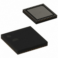
EM250-RTR Ember, EM250-RTR Datasheet - Page 80

EM250-RTR
Manufacturer Part Number
EM250-RTR
Description
IC ZIGBEE SYSTEM-ON-CHIP 48-QFN
Manufacturer
Ember
Series
EM250r
Datasheet
1.EM250-JMP-R.pdf
(117 pages)
Specifications of EM250-RTR
Frequency
2.4GHz
Modulation Or Protocol
802.15.4 Zigbee
Applications
Home/Building Automation, Industrial Control and Monitoring
Power - Output
3dBm
Sensitivity
-97dBm
Voltage - Supply
2 V ~ 3.6 V
Current - Receiving
35.5mA
Current - Transmitting
33mA
Data Interface
PCB, Surface Mount
Memory Size
128kB Flash, 5kB SRAM
Antenna Connector
PCB, Surface Mount
Operating Temperature
-40°C ~ 85°C
Package / Case
48-QFN
For Use With
636-1009 - PROGRAMMER USB FLASH EM250/260
Lead Free Status / RoHS Status
Lead free / RoHS Compliant
Data Rate - Maximum
-
Other names
636-1000-2
Available stocks
Company
Part Number
Manufacturer
Quantity
Price
Company:
Part Number:
EM250-RTR
Manufacturer:
TI
Quantity:
3 400
Part Number:
EM250-RTR
Manufacturer:
EMBER
Quantity:
20 000
EM250
80
120-0082-000I
Table 28), the frequency can be further divided to generate the final timer cycle provided to the timer con-
troller (see Table 29). In addition, the clock edge (either rising or falling) for this timer clock can be selected
(see Table 30).
TMR_CLK[1:0]
0
1
2
3
TMR_PSCL[3:0]
N = 0..10
N = 11..15
TMR_EDGE
0
1
Note: All configuration changes do not take effect until the next edge of the timer's clock source.
These functions are separately controlled for TMR1 and TMR2 by setting the bits
TMR_EDGE
5.4.2
Each timer supports three counting modes: increasing, decreasing, or alternating (where the counting will in-
crease, then decrease, then increase). These modes are controlled by setting the
bits within the
Upward counting continues until the counter value reaches the threshold value stored in the
TMR2_TOP
ternating counting mode is enabled, a triangular-shaped waveform of the count-value can be created. Figure
10 through Figure 13 illustrate the different counting modes available from the timers.
Counting can be enabled and disabled with the register bit
When the timer is disabled, the counter stops counting and maintains its count value. Enabling can be masked
with the pin TMR1ENMSK or TMR2ENMSK, depending on register bit
registers.
By default, the counting operation is repetitive. It can be restricted to single counting enabled with the regis-
ter bit
TMR_1SHOT
Timer Functionality (Counting)
, and
register. Downward counting continues until the counter value reaches the value zero. When the al-
TMR1_CFG
TMR_PSCL
located in the
or
Clock Source
1 kHz RC clock
32.768kHz clock
12 MHz clock
GPIO clock input
Clock Source Prescale Factor
2
2
Clock Source
Rising
Falling
in the timer registers
N
10
TMR2_CFG
Table 28. TMR1 and TMR2 Clock Source Settings
TMR1_CFG
Table 29. Clock Source Divider Settings
registers.
Table 30. Clock Edge Setting
or
TMR2_CFG
TMR1_CFG
registers.
and
TMR_EN
TMR2_CFG
TMR_EXTEN
in the
, respectively.
TMR1_CFG
in the
TMR_CLK
TMR_DOWN
or
TMR1_CFG
TMR2_CFG
,
TMR_FILT
and
TMR1_TOP
or
TMR_BIDIR
registers.
TMR2_CFG
,
or


