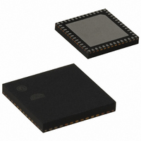
EM250-RTR Ember, EM250-RTR Datasheet - Page 87

EM250-RTR
Manufacturer Part Number
EM250-RTR
Description
IC ZIGBEE SYSTEM-ON-CHIP 48-QFN
Manufacturer
Ember
Series
EM250r
Datasheet
1.EM250-JMP-R.pdf
(117 pages)
Specifications of EM250-RTR
Frequency
2.4GHz
Modulation Or Protocol
802.15.4 Zigbee
Applications
Home/Building Automation, Industrial Control and Monitoring
Power - Output
3dBm
Sensitivity
-97dBm
Voltage - Supply
2 V ~ 3.6 V
Current - Receiving
35.5mA
Current - Transmitting
33mA
Data Interface
PCB, Surface Mount
Memory Size
128kB Flash, 5kB SRAM
Antenna Connector
PCB, Surface Mount
Operating Temperature
-40°C ~ 85°C
Package / Case
48-QFN
For Use With
636-1009 - PROGRAMMER USB FLASH EM250/260
Lead Free Status / RoHS Status
Lead free / RoHS Compliant
Data Rate - Maximum
-
Other names
636-1000-2
Available stocks
Company
Part Number
Manufacturer
Quantity
Price
Company:
Part Number:
EM250-RTR
Manufacturer:
TI
Quantity:
3 400
Part Number:
EM250-RTR
Manufacturer:
EMBER
Quantity:
20 000
5.4.4
There are two capture registers that store the timer count value on a trigger condition from GPIO signals. The
timer trigger signals TMR1IA and TMR1IB for Timer 1, and TMR2IA and TMR2IB for Timer 2 are provided by ex-
ternal signals routed to the GPIO pins.
These timer trigger signals are synchronized to the main 12MHz clock, passed to an optional glitch filter, and
followed by an edge detection circuitry.
These functions are controlled by software with the register bits
TMR1_CAPCFGA
TMR_CAPMOD[1:0]
0
1
2
3
All glitch filters consist of a flip-flop-driven, 4-bit shift register clocked with the main 12MHz clock.
TMROA,TMROB (mode=10)
TMROA,TMROB (mode=11)
TMROA,TMROB (mode=12)
TMROA,TMROB (mode=13)
TMROA,TMROB (mode=14)
TMROA,TMROB (mode=15)
TMROA,TMROB (mode=0)
TMROA,TMROB (mode=1)
TMROA,TMROB (mode=2)
TMROA,TMROB (mode=3)
TMROA,TMROB (mode=4)
TMROA,TMROB (mode=5)
TMROA,TMROB (mode=6)
TMROA,TMROB (mode=7)
TMROA,TMROB (mode=8)
TMROA,TMROB (mode=9)
Timer Functionality (Input Capture)
INT_CMPTOP
INT_WRAP
INT_CMPB
INT_CMPA
INT_CMPZ
CNT
EN
Figure 15. Timer Output Generation Mode Example—Alternating, Non-inverting
,
BIDIR: 1 (ON), DOWN 0 (UP), 1SHOT: 0 (OFF)
TMR1_CAPCFGB
0 = starting CNT < threshold TOP
Detection mode
Disabled
Rising Edge
Falling Edge
Either Edge
,
Table 32. GPIO/Timer Trigger Conditioning
TMR2_CAPCFGA
CMPB
CMPA
0xFFFF
TOP
0x0000
initially low
initially low
initially low
initially low
initially low
initially low
initially low
initially low
initially low
initially low
initially low
initially low
initially low
initially low
initially low
initially low
, and
TMR2_CAPCFGB
TMROA,TMROB (mode=11)
TMROA,TMROB (mode=13)
TMROA,TMROB (mode=14)
TMROA,TMROB (mode=15)
TMROA,TMROB (mode=10)
TMROA,TMROB (mode=12)
TMROA,TMROB (mode=0)
TMROA,TMROB (mode=1)
TMROA,TMROB (mode=2)
TMROA,TMROB (mode=3)
TMROA,TMROB (mode=4)
TMROA,TMROB (mode=5)
TMROA,TMROB (mode=6)
TMROA,TMROB (mode=7)
TMROA,TMROB (mode=8)
TMROA,TMROB (mode=9)
TMR_CAPMOD[1:0]
INT_CMPTOP
INT_WRAP
INT_CMPB
INT_CMPA
INT_CMPZ
registers.
CNT
EN
BIDIR: 1 (ON), DOWN 0 (UP), 1SHOT: 0 (OFF)
0 = starting CNT < threshold TOP
, and
120-0082-000I
TMR_CAPFILT
EM250
TOP
CMPB
CMPA
0xFFFF
0x0000
initially high
initially high
initially high
initially high
initially high
initially high
initially high
initially high
initially high
initially high
initially high
initially high
initially high
initially high
initially high
initially high
in the
87


