M0516ZAN Nuvoton Technology Corporation of America, M0516ZAN Datasheet - Page 248
M0516ZAN
Manufacturer Part Number
M0516ZAN
Description
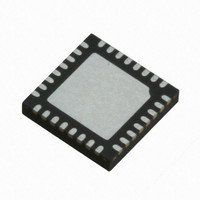
IC MCU 32BIT 64KB FLASH 33QFN
Manufacturer
Nuvoton Technology Corporation of America
Series
NuMicro M051™r
Specifications of M0516ZAN
Core Processor
ARM Cortex-M0
Core Size
32-Bit
Speed
50MHz
Connectivity
EBI/EMI, I²C, IrDA, SPI, UART/USART
Peripherals
Brown-out Detect/Reset, LVD, POR, PWM, WDT
Number Of I /o
24
Program Memory Size
64KB (64K x 8)
Program Memory Type
FLASH
Ram Size
4K x 8
Voltage - Supply (vcc/vdd)
2.5 V ~ 5.5 V
Data Converters
A/D 5x12b
Oscillator Type
Internal
Operating Temperature
-40°C ~ 85°C
Package / Case
33-WFQFN Exposed Pad
Lead Free Status / RoHS Status
Lead free / RoHS Compliant
Eeprom Size
-
Available stocks
Company
Part Number
Manufacturer
Quantity
Price
Company:

Part Number:
M0516ZAN
Manufacturer:
Nuvoton
Quantity:
200
Part Number:
M0516ZAN
Manufacturer:
NUVOTON
Quantity:
20 000


[9:8]
[7:3]
[2]
[1]
[0]
NuMicro M051
TX_NUM
TX_BIT_LEN
TX_NEG
RX_NEG
GO_BUSY
SPI_RX0/1).
Numbers of Transmit/Receive Word
This field specifies how many transmit/receive word numbers should be
executed in one transfer.
00 = Only one transmit/receive word will be executed in one transfer.
01 = Two successive transmit/receive word will be executed in one transfer.
10 = Reserved.
11 = Reserved.
Transmit Bit Length
This field specifies how many bits are transmitted in one transaction. Up to 32
bits can be transmitted.
TX_BIT_LEN = 0x01 … 1 bit
TX_BIT_LEN = 0x02 … 2 bits
……
TX_BIT_LEN = 0x1f … 31 bits
TX_BIT_LEN = 0x00 … 32 bits
Transmit At Negative Edge
0 = The transmitted data output signal is changed at the rising edge of SPICLK.
1 = The transmitted data output signal is changed at the falling edge of SPICLK.
Receive At Negative Edge
0 = The received data input signal is latched at the rising edge of SPICLK.
1 = The received data input signal is latched at the falling edge of SPICLK.
Go and Busy Status
0 = Writing 0 to this bit to stop data transfer if SPI is transferring.
1= In master mode, writing 1 to this bit to start the SPI data transfer; in slave
mode, writing 1 to this bit indicates that the slave is ready to communicate with
a master.
During the data transfer, this bit keeps the value of 1. As the transfer is finished,
this bit will be cleared automatically.
NOTE: All registers should be set before writing 1 to this GO_BUSY bit. When a
transfer is in progress, writing to any register of the SPI/MICROWIRE
master/slave core has no effect.
™
Series Technical Reference Manual
- 248 -
Publication Release Date: Sep 14, 2010
Revision V1.2
Related parts for M0516ZAN
Image
Part Number
Description
Manufacturer
Datasheet
Request
R

Part Number:
Description:
Manufacturer:
Nuvoton Technology Corporation of America
Datasheet:
Part Number:
Description:
Manufacturer:
Nuvoton Technology Corporation of America
Datasheet:
Part Number:
Description:
Manufacturer:
Nuvoton Technology Corporation of America
Datasheet:
Part Number:
Description:
Manufacturer:
Nuvoton Technology Corporation of America
Datasheet:
Part Number:
Description:
Manufacturer:
Nuvoton Technology Corporation of America
Datasheet:
Part Number:
Description:
Manufacturer:
Nuvoton Technology Corporation of America
Datasheet:
Part Number:
Description:
Manufacturer:
Nuvoton Technology Corporation of America
Datasheet: