F39-JC3B Omron, F39-JC3B Datasheet
F39-JC3B
Specifications of F39-JC3B


Related parts for F39-JC3B

F39-JC3B Summary of contents
Page 1
F3SN-A Safety Light Curtain P Series Instruction Manual TYPE 4 PNP Output Type Cat.No. SCEE–713 ...
Page 2
Introduction Thank you for purchasing the F3SN-A Series Safety Light Curtain (hereinafter referred to as "the F3SN-A"). This is the Instruction Manual describing the use of the F3SN-A. Always heed the following points when using the F3SN-A: • Read this ...
Page 3
Give sufficient safety considerations and make enough allowance with regard to ratings and functions of the system when using the F3SN-A under following conditions: (1) Conditions or environment not specified in this manual (2) Applications to devices and facilities requiring ...
Page 4
Always use the two OSSD outputs to configure the safety system. Using only one OSSD of the safety system may result in serious injury when there is an output circuit failure. (Chapter 2-4) Do not connect any of the F3SN-A ...
Page 5
... Use shielded twisted pair cable (cross-sectional area: φ0.3mm communication lines with a cable other than the dedicated cable (F39-JC ), and connect the shield to the 0V line. • When replacing the cable connector with other connectors (e.g. resin connectors), make sure the connector is rated IP54 or higher. • ...
Page 6
... PRIOR TO USE Verify the following items are supplied with each F3SN-A, contact your nearest OMRON representative or distributor if any item is missing. • F3SN-A P • Mounting brackets (top and bottom) qty. 4 • Mounting brackets (intermediate) Supplied with light curtains, which have a mounting interval of 640 mm or more. A maximum of 4 sets is supplied for mounting within 640 mm (2 sets max ...
Page 7
Section 1 Description .........................................................................................................................................1 1-1 Features ......................................................................................................................................................1 1-2 Functions.....................................................................................................................................................2 1-2-1 Interlock function .................................................................................................................................2 1-2-2 Test function ........................................................................................................................................2 1-2-3 Auxiliary Output ...................................................................................................................................3 1-2-4 External indicator output......................................................................................................................3 1-2-5 EDM (External device monitoring).......................................................................................................4 1-2-6 Fixed blanking function (Optional).......................................................................................................4 1-2-7 Floating blanking function (Optional)...................................................................................................4 ...
Page 8
... External test function (Emission stop function) EDM (External device monitoring function) Interlock function Fixed blanking function / Floating blanking function (require set by the F39-MC11) Auxiliary output (Non-safety output) Allows the light curtain status to be transmitted to a PLC or other device. Control Unit: F3SP-B1P (Optional accessory) Allows for quick connection of the light curtain into the safety circuit ...
Page 9
... For the factory setting, the start/restart interlock is selected in the manual reset mode. Other options are selected by the setting console, F39-MC11 (optional). When the light curtain enters the interlock condition, it keeps the OSSD outputs in the OFF-state. Even if all beams become free, the OSSD outputs will not go to the ON-state ...
Page 10
... The diagram on the right shows the timing chart for the Light-ON output mode. For detailed information, refer to the instruction manual for the F39-MC11. The large indicator can be directly attached to the light curtain by using the external indicator F39-A01P - (optional), as shown in the figure on the right, for use with series-connection types only. (*1) ...
Page 11
... F3SN-A can not detect. Failure may result in serious injury. This function is set with the F39-MC11 setting console and disables part of detection zone of the light curtain object enters the disabled detection zone, the OSSD outputs status will not change. This function is used when there is a stationary object in the detection zone that needs to be ignored ...
Page 12
... Series connection Emitter cable F39-JCR2B-L F39-JC1B-L or F39-JC3B-L Emitter Series connection type Emitter cable F39-JC A-L Section 1 Description Safety distance 1 mm Harzardous area P series can connect with the Receiver Series connection Receiver cable F39-JCR2B-D F39-JC1B-D or F39-JC3B-D Receiver Receiver cable F39-JC A-D B-5 ...
Page 13
... In the case the fixed blanking is set in “Lockout mode at the light receiving condition”, the lockout indicator and the blanking indicator flash when the disabled detection zone is not interrupted. In this case, the error mode indicators do not flash. (Refer to the instruction manual of the F39-MC11 for detail.) ...
Page 14
... P25-05 Non-transparent min. in diameter 120 217 to 1822 (n- 0 Light-ON : Dark-ON (can be changed by the F39-MC11) : Light-ON (can be changed by the F39-MC11 voltage : VDC (3 mA max. sink current) OFF voltage : 0 to 1.5 VDC or open Section 1 Description in the type names. F3SN-A P40 F3SN-A F3SN-A ...
Page 15
... For the factory setting, the manual reset mode is set to the start/restart interlock. *4. Using the F39-MC11 can select the start interlock or the restart interlock. For the factory setting, the function is not set. It can be enabled with the F39-MC11. *5. When extending the cable, be sure to use a cable with at least same performance. Do not extend the cable *6 ...
Page 16
Test rod is not supplied with the F3SN-A *7. The intermediate mounting bracket is supplied with the following types: *8. Types which have the total length of the light curtain from 640 mm to 1280 mm: 1 set for each ...
Page 17
Section 1 Description 1-3-2 Response time The response time of OSSD outputs are as follows: F3SN-A P14 series F3SN-A P25 series F3SN-A P40 series F3SN-A P70 series Response time for series connected types is calculated as follows: For 2 sets: ...
Page 18
Section 2 Wiring and Mounting 2-1 Installation Conditions 2-1-1 Detection Zone and Intrusion Path Do not use the F3SN-A on machines that cannot be stopped by electrical control in case of an emergency, such as a pressing machine with full-rotation ...
Page 19
Section 2 Wiring and Mounting 2-1-2 Safety Distance Always maintain a safe distance (S) between the F3SN-A and a hazardous part of a machine. Serious injury may result if the machine does not stop before someone reaches the hazardous part. ...
Page 20
Method for calculating the safety distance as provided by ANSI B11.19 (US) Safety distance (S) = Intrusion speed into the detection zone (K) x Response time ( Tbm) + Additional distance (Dpf) ...(5) Where: ...
Page 21
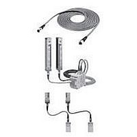
... When using multiple sets of F3SN-A, connect them and/or use light interruption panels to prevent mutual interference. 1) Series connection ( sets, 240 beams, the series connection type is required for connection) Multiple sets of the F3SN-A can be connected in series. Emitter1 Cable F39-JCR2B or F39-JC3B Emitter2 Emitter1 Receiver2 Do not series-connect an emitter to an receiver. An lockout status occurs. ...
Page 22
When not connected When installing two or more light curtains without connecting them to each other due to wiring conditions, considerations must be made to prevent mutual interference. Failure may cause the F3SN into ...
Page 23
Section 2 Wiring and Mounting 2-2 Dimensional Drawings 2-2-1 Side mounting (e.g.: emitter) F3SN-A P Dimensions according to the type can be calculated by using the following equations. F3SN-A P14 series Dimension C2 (Protective height): 4 digits in the type ...
Page 24
The following figures show only dimensions which are different from those of the F3SN-A F3SN-A P -01 F3SN-A P -02 F3SN-A P -03 Section 2 Wiring and Mounting Connector cap M12 Waterproof connector 400 44.7 M12 Waterproof connector Connector cap ...
Page 25
Section 2 Wiring and Mounting The following figures show only dimensions which are different from those of the F3SN-A F3SN-A P -04 F3SN-A P -05 B-18 40.7 200 M12 Waterproof connector 44.7 400 M12 Waterproof connector 40.7 200 M12 Waterproof ...
Page 26
Rear mounting (e.g.: emitter) F3SN-A P Dimensions according to the type can be calculated by using the following equations. F3SN-A P14 series Dimension C2 (Protective height): 4 digits in the type name Dimension Dimension ...
Page 27
Section 2 Wiring and Mounting The following figures show only dimensions which are different from those of the F3SN-A F3SN-A P -01 F3SN-A P -02 F3SN-A P -03 B-20 14 Connector cap M12 Waterproof 400 44.7 M12 Waterproof connector Connector ...
Page 28
The following figures show only dimensions which are different from those of the F3SN-A F3SN-A P -04 F3SN-A P -05 Section 2 Wiring and Mounting M12 Waterproof connector 40.7 200 44.7 400 M12 Waterproof connector M12 Waterproof connector 40.7 200 ...
Page 29
Section 2 Wiring and Mounting 2-3 Mounting 2-3-1 How to Mount the Unit Be sure to have a bend radius of the F3SN-A cable of R36 (mm) or more. Eventual failure of the cable may result. Connector cable Shown below ...
Page 30
Dimensional Drawing of the Mounting Bracket Mounting bracket (top and bottom) Mounting bracket (intermediate) Configuration for rear mounting Configuration for side mounting Section 2 Wiring and Mounting 5.5 6.5 dia. 9 dia. 20 14.2 dia. 22 ...
Page 31
Section 2 Wiring and Mounting Setup procedure when the supplied mounting brackets are used I. Secure the bottom bracket (power connector side wall or column. Secure the intermediate bracket ( wall or II. column. The intermediate ...
Page 32
... Recommended power supply: S82K ( type) made by OMRON. 2) The power supply includes a Class 2 circuit supplied by an isolating source that complies with the requirement in the Standard for Class 2 Power Units, UL 1310, or the requirements in the Standard for Class 2 and Class 3 Transformers, UL 1585 ...
Page 33
... K3: Load, PLC, etc. (Used for monitoring) Wiring when the EDM is not used When the EDM is not necessary 1) Use the F39-MC11 to disable the EDM the auxiliary output is in the "Dark-ON output mode", wire the lines as shown in the figure below to disable the EDM. ...
Page 34
... S2: Interlock/Lockout reset switch KM1, KM2: Relay that control the dangerous zone, etc. K3: Load, PLC, etc. (Used for monitoring) Note1: Use a switch which can apply small load. Note2: If the EDM is not necessary, short-circuit T31 and T32. (Note1 Reset Receiver Receiver cable F39-JC B ...
Page 35
... Section 2 Wiring and Mounting 2-4-3 Wiring Procedures 1. Connect the emitter cable (F39-JC 2. Connect the receiver cable (F39-JC 3. Connect the 0V line of the power supply directly to protective earth (PE). Be sure to wire correctly. Failure may damage the F3SN-A. Confirm the color of cables [Note]: and outer jackets (emitter: gray, receiver: black). Matching colors prevents incorrect wiring. ...
Page 36
... For Receiver Gray outer F39-JCR2B-D Black outer jacket color jacket color F39-JC1B-D F39-JC3B-D F39-JC7B-D F39-JC10B-D F39-JC15B-D L Body color: Gray M12 Waterproof connector Vinil insulated round cable 6.6mm dia. 8cores(4twisted pairs) (conductor cross sectional area: 0.3mm / insulation outside diameter: 1 ...
Page 37
Section 2 Wiring and Mounting 2-4-4 Adjustment Procedures [Procedures] 1. Ensure the following points. • The optical surfaces of the emitter and receiver are clean. • There should be no light-interrupting objects in the F3SN-A detection zone. 2. Adjust the ...
Page 38
Outputs are not shorted to the +24V line. 7. Loads are not connected to the +24V line lines are connected to a commercial supply line. 9. When two or more units are used, they are connected or ...
Page 39
Section 3 I/O Circuit Section 3 I/O Circuit Ext. indicator output 4 Load 7 0V Gray RS-485(A) Gray Ext. indicator output 8 Load 7 0V *1. Open: normal light emission, Short to the +24VDC: stops light emission *2. Refer to ...
Page 40
Output Waveform of the OSSD outputs The OSSD outputs will be OFF as shown in the following figure in order to perform the OSSD circuit self-test when the light curtain is in the ON-state. The OSSD circuit diagnosis is correct ...
Page 41
Section 4 Application Section 4 Application This section shows examples of a motor control system that combines an F3SN-A. These are category 4 systems (EN954-1 provision). Application 1 Emitter Interlock Test selection OSSD1 OSSD2 K1 K2 ...
Page 42
... GND - Combination with the safety relay unit G9SA-301 - Setting of the F3SN-A Auto reset mode Receiver Disabled the EDM function by the F39-MC11 - Setting of the safety relay unit Manual reset mode Using feedback loop - Using a emergency stop switch PLC IN1 IN2 OUT KM3 ...
Page 43
... Some part of the operator’s body remains in the F3SN-A detection zone at all times while working in dangerous machine parts. 3. The actual safety distance is greater than the calculated distance dirt or scratches on the optical surface or the spatter protection cover (the F39-HN, optional) of the F3SN- test rod is not deformed. 6. ...
Page 44
Inspections Every Six Months Inspect the following items every six months or when a machine setting is changed. 1. Machine structure does not hinder stop and other safety functions. 2. There is no machine modification or connection change that ...
Page 45
... Replace with a relay of proper release time, or change the setting value of the relay monitoring time by the F39-MC11. 4) Check the EDM input line and the auxiliary output line for error. Then, confirm that the operation mode for the auxiliary output is in the Dark-ON output mode ...
Page 46
Trouble that the error mode indicator does not flash in the lockout condition If the blanking indicator is flashing, the disable detection zone which set as the fixed blanking in “Lockout mode at the light receiving condition” is not interrupted. ...
Page 47
... F39-A01PR-L F39-A01PG-L F39-A01PR-D F39-A01PG-D B-40 Type Length F39-JC3A 3m F39-JC7A 7m F39-JC10A 10m F39-JC15A 15m Type Length F39-JCR2B 0.2m F39-JC1B 1m F39-JC3B 3m F39-JC7B 7m F39-JC10B 10m F39-JC15B 15m Output Relay (3NO + 1NC) Accessory Branching connector, Connector cap, Cable Applicable Indicator light curtain color Emitter Red ...
Page 48
... The same 4-digit numbers as the protective heights ( by in the type names. *2. The operating range of the light curtain will decrease by 10% when using the spatter protection cover. [Spatter protection cover follows: F39-HN F39-HN [Fixing bracket] 9.9 14 [Mounting dimension] 32.6 Section 7 Optional Accessory Applicable light curtain ...
Page 49
Section 8 Referenced standards Section 8 Referenced standards International Standards - IEC61496-1 Safety of Machinery: Electro-sensitive Protective Equipment – Part 1: General Requirements and Tests - IEC61496-2 Safety of Machinery: Electro-sensitive Protective Equipment – Part 2: Particular Requirements for Equipment ...
Page 50
... The NETHERLANDS Tel: (31)23-5681300 / Fax: (31)23-5681388 OMRON ELECTRONICS LLC 1 East Commerce Drive, Schaumburg, Illinois 60173-5302 U.S.A. Tel: (1)847-843-7900 / Fax: (1)847-843-7787 OMRON ASIA PACIFIC PTE. LTD. 83 Clemenceau Avenue, #11-01, UE Square, Singapore 239920 SINGAPORE Tel: (65)835-3011 / Fax: (65)835-2711 OMRON (CHINA) CO., LTD. Rm 1028, Office Building, Beijing Capital Times Square, No ...