F39-JC3B Omron, F39-JC3B Datasheet - Page 42
F39-JC3B
Manufacturer Part Number
F39-JC3B
Description
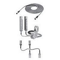
Safety Light Curtain
Manufacturer
Omron
Datasheet
1.F39-JC3B.pdf
(50 pages)
Specifications of F39-JC3B
Light Curtain Type
Safety
Accessory Type
Double-Ended Connector Cable
For Use With
F3SN Series Safety Light Curtain
Lead Free Status / RoHS Status
Lead free / RoHS Compliant


E1
+24VDC
0 V
G9SA-301
Application 3
Application 4
E1
A1
+24VDC
Emitter
A2
0 V
F39-JCxC-L
T11
PE
Emitter
a
T21
K1
K1
T12
6
Vcc
Vcc
GND
GND
b
T23
K2
RS-485(A) (Gray)
RS-485(B) (Pink)
selection
Master
C1
K2
T22
S2
G1
a
b
1
(Note2)
line 2+
Sync
D1
T31
Emitter
A
F3SN Series
Control
TEST
Circuit
J1
K1
K2
line 2-
B
T32
Sync
D2
KM1
KM2
3
4
line 2+
Sync
Receiver
E1
2
5
KM1
13
14
F
A1
line 2-
Sync
E2
G9SA-300-SC
Receiver
23
24
12
11
A2
KM2
33
34
T11
22
21
K3
41
42
F39-JCxC-D
T12
T21
K1
Receiver
K1
OSSD1
JP
H1
K3 K2
S3
T22
K2
1
2
3
4
5
6
IN1
OSSD2
PLC
K3
IN2
Y1
K3
K1
K2
X1
OUT
KM3
KM1
KM2
KM1
KM2
K3
KM1
13
14
- Combination with the safety relay unit G9SA-301
- Setting of the F3SN-A
- Setting of the safety relay unit
- Using a emergency stop switch
Auto reset mode
Disabled the EDM function by the F39-MC11
Manual reset mode
Using feedback loop
S1: External test switch
S2: Reset switch
S3: Emergency stop switch (A165E, or A22E)
KM1, KM2: Magnet contactor (LP1D)
KM3: Solid-state contactor (G3J)
M: 3-phase motor
E1: 24 VDC Power Supply (S82K)
PLC: Programmable Logic Controller
23
24
M
(Used for monitoring. This is not a part of a saety system.)
KM2
33
34
Ext. test SW (S1)
Light interrupted
Emergency stop
SW (S3)
KM1, KM2 N.O.
KM1, KM2 N.C.
Reset SW (S2)
Light reception
K1, K2 N.O.
K1, K2 N.C.
PLC input 1
PLC input 2
PLC output
OSSDs
contact
contact
contact
contact
Section 4 Application
Note1: EDM and Auxiliary output of F3SN cannot be used.
Note2: S2 is open for normal operation and is shorted for
Note3: Nothing should connect with C1,D1,D2,E1and E2.
S1: Reset switch
S2: External test switch
KM1, KM2: Magnet contactor
M: 3-phase motor
E1: 24 VDC Power Supply (S82K)
KM1
KM2
(If the switch is not necessary, open between Vcc and J1.)
extermal test.
Depends on the operation
mode of the auxiliary output
M
Ext. test SW (S2)
Light interrupted
K3 N.O. contact
K3 N.C. contact
KM1, KM2 N.O.
KM1, KM2 N.C.
Reset SW (S1)
Light reception
K1, K2 N.C.
K1, K2 N.O.
OSSDs
contact
contact
contact
contact
B-35
Related parts for F39-JC3B
Image
Part Number
Description
Manufacturer
Datasheet
Request
R

Part Number:
Description:
G6S-2GLow Signal Relay
Manufacturer:
Omron Corporation
Datasheet:
Part Number:
Description:
Compact, Low-cost, SSR Switching 5 to 20 A
Manufacturer:
Omron Corporation
Datasheet:
Part Number:
Description:
Manufacturer:
Omron Corporation
Datasheet:
Part Number:
Description:
Manufacturer:
Omron Corporation
Datasheet:
Part Number:
Description:
Manufacturer:
Omron Corporation
Datasheet:
Part Number:
Description:
Manufacturer:
Omron Corporation
Datasheet:
Part Number:
Description:
Manufacturer:
Omron Corporation
Datasheet:
Part Number:
Description:
Manufacturer:
Omron Corporation
Datasheet: