F39-JC3B Omron, F39-JC3B Datasheet - Page 45
F39-JC3B
Manufacturer Part Number
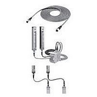
F39-JC3B
Description
Safety Light Curtain
Manufacturer
Omron
Datasheet
1.F39-JC3B.pdf
(50 pages)
Specifications of F39-JC3B
Light Curtain Type
Safety
Accessory Type
Double-Ended Connector Cable
For Use With
F3SN Series Safety Light Curtain
Lead Free Status / RoHS Status
Lead free / RoHS Compliant


Section 6 Troubleshooting
Section 6 Troubleshooting
6-1 Lockout condition
B-38
When the light curtain enters the lockout condition, the error content will be displayed by a flashing pattern
of the Error mode indicator.
Devise a countermeasure in accordance with the following table.
Flashing Not lit
[Note]:
Error mode
indicator
A B C
A B C
A B C
A B C
A B C
A B C
A B C
For some error conditions, either only the emitter or receiver will flash.
Wiring error for
interlock function
setting
Error of the EDM
function
RS-485
communication
line error
OSSD error
Error by
interference light
Incorrect
configuration on
the light curtain
connection
Error by noises
or Destruction of
the light curtain
1) The reset input line and the
interlock selection input line are not
wired correctly.
2) The interlock selection input line
became open or shorted during
power-on.
1) One of the external relay contacts
is welded.
2) The EDM input line is not wired
correctly to the external relays.
3) The setting value of relay
monitoring time is lower than the
relay response time.
4) In the case of connecting the EDM
input line to the auxiliary output line in
order to make the EDM function
inactive, lines are open or shorted to
the 0 V line.
1) The RS-485 communication line is
open or shorted to the other I/O line.
2) Communication error by noises.
3) When the light curtains are
connected in series, the connector of
the series connection cable is
disconnected.
4) Failure of the CPU.
1) OSSD outputs are shorted
together
2) At least one OSSD output is
shorted to the +24V line, 0V line, or
the other I/O line.
3) Failure of OSSD output circuit
1) Interference light is received.
2) The emission light of the other
photoelectric sensor is received.
1) The type of the receiver is different
from the type of the emitter. (e.g. the
number of beams is different.)
2) The number of the receiver
connected in series is different from
that of the emitter.
1) Influenced by significant noise.
2) Internal hardware failure of the
receiver or the emitter.
Cause
1)-2)
Confirms the wiring for the auto reset
mode or the manual reset mode.
1) Replace the relay.
2) Check connection of the relay
monitoring input line.
3) Replace with a relay of proper
release time, or change the setting
value of the relay monitoring time by
the F39-MC11.
4) Check the EDM input line and the
auxiliary output line for error. Then,
confirm that the operation mode for
the auxiliary output is in the Dark-ON
output mode.
1) Check connection of the RS-485
lines.
2) Check noise environment around
the RS-485 communication lines.
3) Check the cable connection
between the light curtains connected
in series.
4) Replace the light curtain
1)-2) Rewire the OSSD outputs
correctly.
3) Replace the receiver.
1)-2) Interrupt the interference light.
(Refer to 2-1-4)
1)-2)
Correct the type or the number of the
light curtain connected in series.
1) Check noise environment around
the light curtain.
2) Replace the receiver or the
emitter.
Remedy
Related parts for F39-JC3B
Image
Part Number
Description
Manufacturer
Datasheet
Request
R

Part Number:
Description:
G6S-2GLow Signal Relay
Manufacturer:
Omron Corporation
Datasheet:
Part Number:
Description:
Compact, Low-cost, SSR Switching 5 to 20 A
Manufacturer:
Omron Corporation
Datasheet:
Part Number:
Description:
Manufacturer:
Omron Corporation
Datasheet:
Part Number:
Description:
Manufacturer:
Omron Corporation
Datasheet:
Part Number:
Description:
Manufacturer:
Omron Corporation
Datasheet:
Part Number:
Description:
Manufacturer:
Omron Corporation
Datasheet:
Part Number:
Description:
Manufacturer:
Omron Corporation
Datasheet:
Part Number:
Description:
Manufacturer:
Omron Corporation
Datasheet: