F39-JC3B Omron, F39-JC3B Datasheet - Page 31
F39-JC3B
Manufacturer Part Number
F39-JC3B
Description
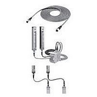
Safety Light Curtain
Manufacturer
Omron
Datasheet
1.F39-JC3B.pdf
(50 pages)
Specifications of F39-JC3B
Light Curtain Type
Safety
Accessory Type
Double-Ended Connector Cable
For Use With
F3SN Series Safety Light Curtain
Lead Free Status / RoHS Status
Lead free / RoHS Compliant


Section 2 Wiring and Mounting
B-24
Setup procedure when the supplied mounting brackets are used
I.
II.
III. Align the intermediate bracket (2) with the
IV. Insert the cable connector of the light curtain into
V. Move the intermediate bracket (2) until its height
VI. After having aligned the intermediate bracket (2)
VII. Align the top bracket (cap side) with the round
VIII. Insert two supplied screws (M4x8) into both top
IX. Adjust the torsion angle of the light curtain in the
X. Securely tighten the bottom and top brackets.
XI. Then, securely tighten the intermediate brackets.
Secure the bottom bracket (power connector
side) on a wall or column.
Secure the intermediate bracket (3) on a wall or
column.
[Note]:
protrusion of intermediate bracket (1) located on
the rear side of the light curtain, and temporarily
tighten the supplied screw (M4x6).
[Note]:
the bottom bracket.
is aligned with that of the intermediate bracket
(3)(V-a), securely tighten the screw (M4x6)(V-b).
[Note]:
with the intermediate bracket (3) in the direction
of mounting the light curtain, temporarily tighten
the supplied screw (M5x8).
Intermediate brackets (2) and (3) are assembled
in the following three ways; VI-a, VI-b, VI-c.
hole on the cap, and secure it on a wall or
column.
and bottom brackets, and temporary tighten
them (VIII-a, VIII-b). (The figure shown below
describes the side mounting.)
point where the five light receiving level indicators
are lit.
The procedure to mount the light curtain is now complete.
Intermediate bracket (3)
Intermediate bracket (2)
The intermediate bracket(3) of the
receiver is mounted upside down
compared with that of the emitter.
Mount the intermediate bracket (2) so
that its direction is the same as that of the
intermediate bracket (3).
Be sure to perform this step prior to
mounting the top bracket (cap side).
Bottom bracket
Top bracket
[Rear mounting]
Emitting
surface
I.
IV.
VI-a.
VII.
Rear mounting
IX.
[Side mounting]
II.
Side mounting (1)
VI-b.
VIII-a.
V-a.
X.
III.
VI-c.
Side mounting (2)
VIII-b.
V-b.
XI.
Related parts for F39-JC3B
Image
Part Number
Description
Manufacturer
Datasheet
Request
R

Part Number:
Description:
G6S-2GLow Signal Relay
Manufacturer:
Omron Corporation
Datasheet:
Part Number:
Description:
Compact, Low-cost, SSR Switching 5 to 20 A
Manufacturer:
Omron Corporation
Datasheet:
Part Number:
Description:
Manufacturer:
Omron Corporation
Datasheet:
Part Number:
Description:
Manufacturer:
Omron Corporation
Datasheet:
Part Number:
Description:
Manufacturer:
Omron Corporation
Datasheet:
Part Number:
Description:
Manufacturer:
Omron Corporation
Datasheet:
Part Number:
Description:
Manufacturer:
Omron Corporation
Datasheet:
Part Number:
Description:
Manufacturer:
Omron Corporation
Datasheet: