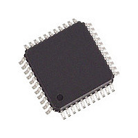
82V2041EPPG IDT, Integrated Device Technology Inc, 82V2041EPPG Datasheet - Page 14

82V2041EPPG
Manufacturer Part Number
82V2041EPPG
Description
Manufacturer
IDT, Integrated Device Technology Inc
Datasheet
1.82V2041EPPG.pdf
(75 pages)
Specifications of 82V2041EPPG
Number Of Transceivers
1
Screening Level
Industrial
Mounting
Surface Mount
Package Type
TQFP
Operating Temperature (min)
-40C
Operating Temperature (max)
85C
Lead Free Status / RoHS Status
Compliant
- Current page: 14 of 75
- Download datasheet (2Mb)
Table-1 Pin Description (Continued)
Pin Description
IDT82V2041E
GNDIO
VDDIO
GNDT
VDDA
GNDA
VDDD
GNDD
Name
VDDT
RST
THZ
JA1
JA0
IC
IC
Type
-
-
-
-
-
-
-
-
-
-
I
I
I
I
Pin No.
15
14
12
13
19
18
35
38
42
39
10
34
44
8
JA[1:0]: Jitter attenuation position, bandwidth and the depth of FIFO select (only used for hardware control mode)
•
•
•
•
In software control mode, this pin should be connected to ground.
See above.
RST: Hardware reset
The chip is forced to reset state if a low signal is input on this pin for more than 100 ns. MCLK must be active during reset.
THZ: Transmitter Driver High Impedance Enable
This signal enables or disables transmitter driver. A low level on this pin enables the driver while a high level on this pin places
driver in high impedance state. Note that the functionality of the internal circuits is not affected by this signal.
3.3 V I/O power supply
I/O ground
3.3 V power supply for transmitter driver
Analog ground for transmitter driver
3.3 V analog core power supply
Analog core ground
Digital core power supply
Digital core ground
IC: Internal connection
Internal Use. This pin should be left open when in normal operation.
IC: Internal connection
Internal Use. This pin should be connected to ground when in normal operation.
00 = JA is disabled
01 = JA in receiver, broad bandwidth, FIFO=64 bits
10 = JA in receiver, narrow bandwidth, FIFO=128 bits
11 = JA in transmitter, narrow bandwidth, FIFO=128 bits
Power Supplies and Grounds
SINGLE CHANNEL T1/E1/J1 SHORT HAUL LINE INTERFACE UNIT
Others
14
Description
December 9, 2005
Related parts for 82V2041EPPG
Image
Part Number
Description
Manufacturer
Datasheet
Request
R

Part Number:
Description:
TRANSLATION DEVICE DPI 80-PQFP
Manufacturer:
IDT, Integrated Device Technology Inc
Datasheet:

Part Number:
Description:
IDT PART
Manufacturer:
IDT, Integrated Device Technology Inc
Datasheet:

Part Number:
Description:
IC LIU T1/E1/J1 OCTAL 256PBGA
Manufacturer:
IDT, Integrated Device Technology Inc
Datasheet:

Part Number:
Description:
IC FREQ TIMING GENERATOR 28TSSOP
Manufacturer:
IDT, Integrated Device Technology Inc
Datasheet:

Part Number:
Description:
IC CLK DVR PLL 1:10 40VFQFPN
Manufacturer:
IDT, Integrated Device Technology Inc
Datasheet:

Part Number:
Description:
IC CLK FANOUT BUFFER 1:18 32LQFP
Manufacturer:
IDT, Integrated Device Technology Inc
Datasheet:

Part Number:
Description:
IC CLK FANOUT BUFFER 1:18 32LQFP
Manufacturer:
IDT, Integrated Device Technology Inc
Datasheet:

Part Number:
Description:
IC CK505 VREG/RES 56TSSOP
Manufacturer:
IDT, Integrated Device Technology Inc
Datasheet:

Part Number:
Description:
IC SDRAM CLK DVR 1:10 48-TSSOP
Manufacturer:
IDT, Integrated Device Technology Inc
Datasheet:

Part Number:
Description:
IC CLK DVR PLL 1:10 48TSSOP
Manufacturer:
IDT, Integrated Device Technology Inc
Datasheet:

Part Number:
Description:
IC FLEXPC CLK PROGR P4 56-TSSOP
Manufacturer:
IDT, Integrated Device Technology Inc
Datasheet:

Part Number:
Description:
IC FLEXPC CLK PROGR P4 56-TSSOP
Manufacturer:
IDT, Integrated Device Technology Inc
Datasheet:

Part Number:
Description:
IC FLEXPC CLK PROGR P4 56-SSOP
Manufacturer:
IDT, Integrated Device Technology Inc
Datasheet:

Part Number:
Description:
IC PLL CLK DRIVER 2.5V 28-TSSOP
Manufacturer:
IDT, Integrated Device Technology Inc
Datasheet:

Part Number:
Description:
IC CLOCK DRIVER 2.5V 24-TSSOP
Manufacturer:
IDT, Integrated Device Technology Inc
Datasheet:


