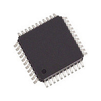
82V2041EPPG IDT, Integrated Device Technology Inc, 82V2041EPPG Datasheet - Page 38

82V2041EPPG
Manufacturer Part Number
82V2041EPPG
Description
Manufacturer
IDT, Integrated Device Technology Inc
Datasheet
1.82V2041EPPG.pdf
(75 pages)
Specifications of 82V2041EPPG
Number Of Transceivers
1
Screening Level
Industrial
Mounting
Surface Mount
Package Type
TQFP
Operating Temperature (min)
-40C
Operating Temperature (max)
85C
Lead Free Status / RoHS Status
Compliant
4.3
4.3.1
Table-20 ID: Device Revision Register
Table-21 RST: Reset Register
Table-22 GCF: Global Configuration Register
Table-23 TERM: Transmit and Receive Termination Configuration Register
Programming Information
IDT82V2041E
R_TERM[2:0]
T_TERM[2:0]
INT_PIN[1:0]
RST[7:0]
Symbol
Symbol
Symbol
Symbol
ID[7:0]
T1E1
REGISTER DESCRIPTION
CONTROL REGISTERS
-
-
(R, Address = 00H)
(W, Address = 01H)
(R/W, Address = 02H)
(R/W, Address = 03H)
7-0
7-0
7-3
1-0
7-6
5-3
2-0
Bit
Bit
Bit
Bit
2
Default
Default
Default
Default
00000
00H
00H
000
000
00
00
0
Current silicon chip ID.
Software reset. A write operation on this register will reset all internal registers to their default values, and the status
of all ports are set to the default status. The content in this register can not be changed. After reset, all drivers output
are in high impedance state.
Note: Bit T1E1 (GCF0) will keep set value and will not be reset.
Reserved.
This bit selects the E1 or T1/J1 operation mode globally.
= 0: E1 mode is selected.
= 1: T1/J1 mode is selected.
to be settled.
Interrupt pin control
= x0: Open drain, active low (with an external pull-up resistor)
= 01: Push-pull, active low
= 11: Push-pull, active high
Reserved.
These bits select the internal termination for transmit line impedance matching.
= 000: Internal 75 Ω impedance matching
= 001: Internal 120 Ω impedance matching
= 010: Internal 100 Ω impedance matching
= 011: Internal 110 Ω impedance matching
= 1xx: Selects external impedance matching resistors for E1 mode only. T1/J1 does not require external impedance
resistors (see Table-10).
These bits select the internal termination for receive line impedance matching.
= 000: Internal 75 Ω impedance matching
= 001: Internal 120 Ω impedance matching
= 010: Internal 100 Ω impedance matching
= 011: Internal 110 Ω impedance matching
= 1xx: Selects external impedance matching resistors (see Table-11).
Note: After bit T1E1 is changed: Before accessing any other regisers a delay of 50us is required to allow the internal clocking
SINGLE CHANNEL T1/E1/J1 SHORT HAUL LINE INTERFACE UNIT
38
Description
Description
Description
Description
December 9, 2005


