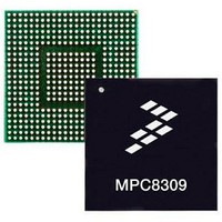
MPC8309VMAHFCA Freescale Semiconductor, MPC8309VMAHFCA Datasheet - Page 77

MPC8309VMAHFCA
Manufacturer Part Number
MPC8309VMAHFCA
Description
417/333/233 MP Std Tmp
Manufacturer
Freescale Semiconductor
Datasheet
1.MPC8309VMAHFCA.pdf
(81 pages)
Specifications of MPC8309VMAHFCA
Processor Series
MPC8309
Core
e300c3
Data Bus Width
32 bit
Data Ram Size
512 MB
Interface Type
USB, CAN, UART, PCI
Maximum Clock Frequency
417 MHz
Number Of Programmable I/os
56
Operating Supply Voltage
- 0.3 V to + 1.26 V
Maximum Operating Temperature
+ 105 C
Mounting Style
SMD/SMT
Operating Temperature Range
0 C to + 105 C
Processor To Be Evaluated
MPC8309
Supply Current (max)
5 uA
Lead Free Status / Rohs Status
Details
Available stocks
Company
Part Number
Manufacturer
Quantity
Price
Company:
Part Number:
MPC8309VMAHFCA
Manufacturer:
Freescale Semiconductor
Quantity:
10 000
to minimize inductance. Suggested bulk capacitors—100 to 330 µF (AVX TPS tantalum or Sanyo
OSCON).
25.4
For all buses, the driver is a push-pull single-ended driver type (open drain for I
To measure Z
or GND. Then, the value of each resistor is varied until the pad voltage is OV
output impedance is the average of two components, the resistances of the pull-up and pull-down devices.
When data is held high, SW1 is closed (SW2 is open) and R
OV
other in value. Then, Z
The value of this resistance and the strength of the driver’s current source can be found by making two
measurements. First, the output voltage is measured while driving logic 1 without an external differential
termination resistor. The measured voltage is V
while driving logic 1 with an external precision differential termination resistor of value R
measured voltage is V
R
Freescale Semiconductor
source
DD
MPC8309 PowerQUICC II Pro Integrated Communications Processor Family Hardware Specifications, Rev. 1
/2. R
= R
Output Buffer DC Impedance
term
P
then becomes the resistance of the pull-up devices. R
0
for the single-ended drivers, an external resistor is connected from the chip pad to OV
(V
1
/V
2
0
2
= (1/(1/R
= (R
– 1). The drive current is then I
P
+ R
Figure 47. Driver Impedance Measurement
1
Data
N
+ 1/R
)/2.
2
)) I
1
source
= R
source
. Solving for the output impedance gives
source
I
P
Pad
R
R
source
is trimmed until the voltage at the pad equals
N
P
OGND
OV
= V
DD
P
. Second, the output voltage is measured
1
and R
/R
SW2
SW1
source
N
are designed to be close to each
.
DD
2
/2 (see
C).
System Design Information
Figure
term
. The
47). The
DD
77


