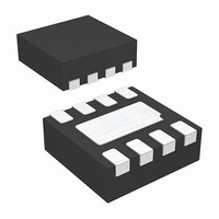
ISL29004IROZ Intersil, ISL29004IROZ Datasheet - Page 10

ISL29004IROZ
Manufacturer Part Number
ISL29004IROZ
Description
IC SENSOR LIGHT-DGTL I2C 8-ODFN
Manufacturer
Intersil
Series
-r
Datasheet
1.ISL29004IROZ-EVALZ.pdf
(17 pages)
Specifications of ISL29004IROZ
Wavelength
550nm
Output Type
I²C™
Package / Case
8-WFDFN Exposed Pad
Lead Free Status / Rohs Status
Lead free / RoHS Compliant
Since fosc is dual speed depending on the Gain/Range bit,
T
and n is:
T
INTEGRATION TIME IN EXTERNAL TIMING MODE
This timing mode is programmed in the command register
00(hex) bit 5. External Timing Mode is recommended when
integration time can be synchronized to an external signal
such as a PWM to eliminate noise.
For Mode0 or Mode1 operation, the integration starts when
the sync_iic command is sent over the I
needs two sync_iic commands to complete a photodiode
conversion. The integration then stops when another
sync_iic command is received. Writing a logic 1 to the
sync_iic bit ends the current adc integration and starts
another one.
For Mode3, the operation is a sequential Mode0 and Mode1.
The device needs three sync_iic commands to complete two
photodiode measurments. The 1st sync_iic command starts
the conversion of the diode1. The 2nd sync_iic completes the
conversion of diode1 and starts the conversion of diode2. The
3rd sync_iic pules ends the conversion of diode2 and starts
over again to commence conversion of diode1.
The integration time, T
equation:
i
f
T
T
TABLE 13. INTEGRATION TIMES FOR TYPICAL
*Integration time in milliseconds
**Recommended
I2C
I2C
int
int
int
int
T
configured for Internal Timing Mode and Gain/Range is set
to Range1 or Range2.
T
configured for Internal Timing Mode and Gain/Range is set
to Range3 or Range4.
R
100**
1
int1
int2
(kΩ)
2
200
500
is dual time. The integration time as a function of R
is the number of I
EXT
50
is the I
=
=
=
i
----------
f
I2C
is the integration time when the the device is
is the integration time when the the device is
I2C
2
2
n
n
×
×
2
100
200
400
1000
--------------------------------------------- -
327kHz 100kΩ
C operating frequency
--------------------------------------------- -
655kHz 100kΩ
n = 16-BIT
R
R
R
EXT resistor value
EXT
EXT
RANGE1
RANGE2
×
×
2
int
C clock cycles to obtain the T
6.4
13
26
64
, is determined by the following
n = 12-BIT
10
13
26
52
128
n = 12-BIT
2
C lines. The device
RANGE3
RANGE4
R
EXT VALUES
0.013
0.025
0.050
0.125
int.
n = 4
(EQ. 12)
(EQ. 11)
(EQ. 10)
EXT
ISL29004
The internal oscillator, f
internal and external timing modes, with the same
dependence on R
the number of clock cycles per integration is no longer fixed
at 2
integration time, and is limited to 2
avoid erroneous Lux readings the integration time must be
short enough not to allow an overflow in the counter register.
Noise Rejection
In general, integrating type ADC’s have an excellent noise-
rejection characteristics for periodic noise sources whose
frequency is an integer multiple of the integration time. For
instance, a 60Hz AC unwanted signal’s sum from 0ms to
k*16.66ms (k = 1,2...k
integration time to be an integer multiple of the periodic
noise signal, greatly improves the light sensor output signal
in the presence of noise.
Design Example 1
The ISl29004 will be designed in a portable system. The
ambient light conditions that the device will be exposed to is
at most 500Lux which is a good office lighting. The light
source has a 50/60Hz power line noise which is not visible
by the human eye. The I2C clock is 10kHz.
Solution 1 - Using Internal Timing Mode
In order to achieve both 60Hz and 50Hz AC noise rejection,
the integration time needs to be adjusted to coincide with an
integer multiple of the AC noise cycle times.
The first instance of integer values at which T
60Hz and 50Hz is when i = 6, and j= 5.
Next, the Gain/Range needs to be determined. Based on the
application condition given, Lux(max) = 500Lux, a range of
1000Lux is desirable. This corresponds to a Gain/Range
Range1 mode. Also impose a resolution of n = 16-bit. Hence
we choose equation 10 to determine R
T
for Internal Timing Mode and Gain/Range is set to Range3 or Range
R
R
int
f
Range1 or Range2.
f
Range3 or Range4.
T
T
T
EXT
EXT
osc
osc
int
int
int
n
<
. The number of clock cycles varies with the chosen
65,535
----------------- -
= i(1/60Hz) = j(1/50Hz).
= 6(1/60Hz) = 5(1/50Hz)
f
= 327kHz*100kΩ/R
= 655kHz*100kΩ/R
= 100ms
=
=
OSC
T
---------------------------------------------------------------- -
50kΩ
int
×
327kHz
2
EXT
n
×
. However, in External Timing Mode,
i
) is zero. Similarly, setting the device’s
100
OSC
kΩ
EXT
EXT
, operates identically in both the
. When Range/Gain is set to
. When Range/Gain is set to
16
= 65,536. In order to
EXT
.
int
December 21, 2006
rejects both
(EQ. 13)
(EQ. 14)
FN6221.0


