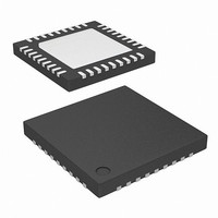
ISL97650ARTZ-T Intersil, ISL97650ARTZ-T Datasheet - Page 13

ISL97650ARTZ-T
Manufacturer Part Number
ISL97650ARTZ-T
Description
IC LCD SUPPLY HP 4CHN 36-TQFN
Manufacturer
Intersil
Datasheet
1.ISL97650ARTZ-TK.pdf
(20 pages)
Specifications of ISL97650ARTZ-T
Applications
LCD TV/Monitor
Current - Supply
250µA
Voltage - Supply
4 V ~ 14 V
Operating Temperature
-40°C ~ 105°C
Mounting Type
Surface Mount
Package / Case
36-TQFN
Lead Free Status / RoHS Status
Lead free / RoHS Compliant
Available stocks
Company
Part Number
Manufacturer
Quantity
Price
Part Number:
ISL97650ARTZ-T
Manufacturer:
INTERSIL
Quantity:
20 000
Cascaded MOSFET Application
An 20V N-channel MOSFET is integrated in the boost
regulator. For the applications where the output voltage is
greater than 20V, an external cascaded MOSFET is needed
as shown in Figure 15. The voltage rating of the external
MOSFET should be greater than A
Buck Converter
The buck converter is the step down converter, which
supplies the current to the logic circuit of the LCD system.
The ISL97650 integrates an 20V N-channel MOSFET to
save cost and reduce external component count. In the
continuous current mode, the relationship between input
voltage and output voltage is as shown in Equation 10:
Where D is the duty cycle of the switching MOSFET.
Because D is always less than 1, the output voltage of buck
converter is lower than input voltage.
The peak current limit of buck converter is set to 2A, which
restricts the maximum output current (average) based on
Equation 11:
Where ΔI
Equation 12,
Where L is the buck inductor, f
(1.2MHz).
V
--------------------- -
I
ΔI
OMAX
V
FIGURE 15. CASCADED MOSFET TOPOLOGY FOR HIGH
LOGIC
V
pp
IN
IN
=
=
V
--------------------- -
=
LOGIC
L f
2A ΔI
pp
⋅
D
s
–
is the ripple current in the buck inductor as
OUTPUT VOLTAGE APPLICATIONS
INTERSIL
ISL97650
⋅
pp
(
1 D
–
)
13
LX1, LX2
s
is the switching frequency
VDD
FBB
.
(EQ. 10)
(EQ. 12)
(EQ. 11)
A
VDD
ISL97650
Feedback Resistors
The buck converter output voltage is determined by the
Equation 13:
Where R14 and R15 are the feedback resistors of buck
converter to set the output voltage. Current drawn by the
resistor network should be limited to maintain the overall
converter efficiency. The maximum value of the resistor
network is limited by the feedback input bias current and the
potential for noise being coupled into the feedback pin. A
resistor network in the order of 1kΩ is recommended.
Buck Converter Input Capacitor
The capacitor should support the maximum AC RMS current
which happens when D = 0.5 and maximum output current.
Where I
shows some recommendations for input capacitors.
Buck Inductor
An 3.3µH to 10µH inductor is the good choice for the buck
converter. Besides the inductance, the DC resistance and
the saturation current are also the factor needed to be
considered when choosing buck inductor. Low DC
resistance can help maintain high efficiency, and the
saturation current rating should be 2A. Here are some
recommendations for buck inductor.
V
I
acrms
CAPACITOR
INDUCTOR
LOGIC
2.7A
2.4A
TABLE 6. INPUT CAPACITOR (BUCK) RECOMMENDATION
10µF/16V
10µF/10V
22µF/16V
3A
4.7µH/
6.8µH/
10µH/
PEAK
PEAK
PEAK
(
TABLE 7. BUCK INDUCTOR RECOMMENDATION
C
o
=
IN
is the output current of the buck converter. Table 6
)
R
-------------------------- -
14
=
R
DIMENSIONS
12.95x9.4x3.0 Coilcraft
+
15
5.7x5.0x4.7
7.3x6.8x3.2
SIZE
1206
0805
1210
D
R
⋅
(mm)
15
(
1 D
×
–
V
TDK
Murata
Murata
FBL
)
⋅
I
O
VENDOR
Murata
TDK
VENDOR
LQH55DN4R7M01K
RLF7030T-6R8M2R8
DO3308P-103
GRM21BR61A106K
C3216X7R1C106M
C3225X7R1C226M
PART NUMBER
PART NUMBER
April 17, 2009
(EQ. 13)
(EQ. 14)
FN9198.4


