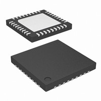
ISL97650ARTZ-T Intersil, ISL97650ARTZ-T Datasheet - Page 19

ISL97650ARTZ-T
Manufacturer Part Number
ISL97650ARTZ-T
Description
IC LCD SUPPLY HP 4CHN 36-TQFN
Manufacturer
Intersil
Datasheet
1.ISL97650ARTZ-TK.pdf
(20 pages)
Specifications of ISL97650ARTZ-T
Applications
LCD TV/Monitor
Current - Supply
250µA
Voltage - Supply
4 V ~ 14 V
Operating Temperature
-40°C ~ 105°C
Mounting Type
Surface Mount
Package / Case
36-TQFN
Lead Free Status / RoHS Status
Lead free / RoHS Compliant
Available stocks
Company
Part Number
Manufacturer
Quantity
Price
Part Number:
ISL97650ARTZ-T
Manufacturer:
INTERSIL
Quantity:
20 000
Layout Recommendation
The device's performance including efficiency, output noise,
transient response and control loop stability is dramatically
affected by the PCB layout. PCB layout is critical, especially
at high switching frequency.
There are some general guidelines for layout:
A demo board is available to illustrate the proper layout
implementation.
Intersil products are sold by description only. Intersil Corporation reserves the right to make changes in circuit design, software and/or specifications at any time without
notice. Accordingly, the reader is cautioned to verify that data sheets are current before placing orders. Information furnished by Intersil is believed to be accurate and
reliable. However, no responsibility is assumed by Intersil or its subsidiaries for its use; nor for any infringements of patents or other rights of third parties which may result
from its use. No license is granted by implication or otherwise under any patent or patent rights of Intersil or its subsidiaries.
1. Place the external power components (the input
2. Place V
3. Reduce the loop with large AC amplitudes and fast slew
4. The feedback network should sense the output voltage
5. The power ground (PGND) and signal ground (SGND)
6. The exposed die plate, on the underneath of the
7. To minimize the thermal resistance of the package when
8. Minimize feedback input track lengths to avoid switching
capacitors, output capacitors, boost inductor and output
diodes, etc.) in close proximity to the device. Traces to
these components should be kept as short and wide as
possible to minimize parasitic inductance and resistance.
rate.
directly from the point of load, and be as far away from LX
node as possible.
pins should be connected at only one point.
package, should be soldered to an equivalent area of
metal on the PCB. This contact area should have multiple
via connections to the back of the PCB as well as
connections to intermediate PCB layers, if available, to
maximize thermal dissipation away from the IC.
soldered to a multi-layer PCB, the amount of copper track
and ground plane area connected to the exposed die
plate should be maximized and spread out as far as
possible from the IC. The bottom and top PCB areas
especially should be maximized to allow thermal
dissipation to the surrounding air.
noise pick-up.
REF
All Intersil U.S. products are manufactured, assembled and tested utilizing ISO9000 quality systems.
and V
Intersil Corporation’s quality certifications can be viewed at www.intersil.com/design/quality
DC
For information regarding Intersil Corporation and its products, see www.intersil.com
bypass capacitors close to the pins.
19
ISL97650
April 17, 2009
FN9198.4


