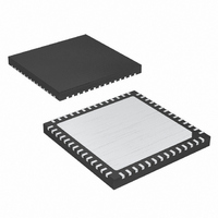
MAX8655ETN+T Maxim Integrated Products, MAX8655ETN+T Datasheet - Page 12

MAX8655ETN+T
Manufacturer Part Number
MAX8655ETN+T
Description
IC STEP-DN REG 25A 56-TQFN-EP
Manufacturer
Maxim Integrated Products
Type
Step-Down (Buck)r
Datasheet
1.MAX8655ETNT.pdf
(23 pages)
Specifications of MAX8655ETN+T
Internal Switch(s)
Yes
Synchronous Rectifier
No
Number Of Outputs
1
Voltage - Output
0.7 ~ 5.5 V
Current - Output
25A
Frequency - Switching
200kHz ~ 1MHz
Voltage - Input
4.5 ~ 25 V
Operating Temperature
-40°C ~ 85°C
Mounting Type
Surface Mount
Package / Case
56-TQFN Exposed Pad
Lead Free Status / RoHS Status
Lead free / RoHS Compliant
Power - Output
-
Lead Free Status / Rohs Status
Lead free / RoHS Compliant
Highly Integrated, 25A, Wide-Input,
Internal MOSFET, Step-Down Regulator
A flying capacitor boost circuit (Figure 2) generates the
gate-drive voltage for the internal high-side n-channel
MOSFET. The capacitor between BST and LXB is
charged from VL to 6.5V minus the diode forward-volt-
age drop while the low-side MOSFET is on. When the
low-side MOSFET is switched off, the stored voltage of
the capacitor is stacked above LXB to provide the nec-
essary turn-on voltage (V
An internal switch between BST and the internal high-
side MOSFET’s gate closes to turn the MOSFET on.
The current-sense circuit amplifies the differential cur-
rent-sense voltage (V
rent-sense signal and the internal-slope-compensation
signal are summed (V
PWM comparator’s inverting input. The PWM compara-
tor shuts off the high-side MOSFET when V
exceeds the integrated feedback voltage (V
The differential current sense is also used to provide
peak inductor current limiting. This current limit is more
accurate than the valley current limit, which is measured
across the internal low-side MOSFET.
The MAX8655 uses both foldback and peak current lim-
iting. The valley foldback current limit is used to reduce
power dissipation of external components—mainly the
inductor, internal power MOSFETs, and the upstream
power source, when the output is severely overloaded
or short circuited and when POK is low. Thus, the circuit
can withstand short-circuit conditions continuously with-
out causing overheating of any component. The peak
constant current limit sets the current-limit point more
accurately since it does not have to suffer the wide vari-
ation of the low-side power MOSFET’s on-resistance
due to tolerance and temperature.
Figure 2. High-Side Gate Boost Circuit
12
______________________________________________________________________________________
High-Side Gate-Drive Supply (BST)
MAX8655
VL
CS+
SUM
Current-Sense Amplifier
GS
- V
BST
LXB
) together and fed into the
) for the high-side MOSFET.
Current-Limit Circuit
CS-
). This amplified cur-
COMP
).
SUM
The valley current is sensed across the on-resistance of
the low-side MOSFET. The valley current limit trips when
the sensed current exceeds the valley current limit.
Set the minimum valley current limit when the output
voltage is at its nominal regulated value, higher than
the maximum peak current-limit setting. With this
method, the current-limit point accuracy is controlled
by the peak current limit and is not interfered with by
the wide variation of the MOSFET’s on-resistance. See
the Setting the Current Limit section for how to set
these limits.
The MAX8655 can be configured for either an
adjustable valley current-limit threshold with adjustable
foldback ratio or a fixed valley current limit that latches
the regulator off. To use foldback current limit with
autorecovery, connect MODE to GND. When the latch-off
mode is used, connect MODE to AVL and set the cur-
rent-limit threshold with one resistor from ILIM2 to GND.
Cycle EN or input power to reset the current-limit latch.
The peak current limit is used to sense the inductor cur-
rent, and is more accurate than the valley current limit
because it does not depend upon the on-resistance of
the low-side MOSFET. The peak current can be mea-
sured across the resistance of the inductor for the high-
est efficiency, or alternatively, a current-sense resistor
can be used for more accurate current sensing. A
resistor connected from ILIM1 to GND sets the peak
current-limit threshold.
For more information on the current limit, see the
Setting the Current Limit section.
The MAX8655 has an adjustable internal oscillator that
can be set to any frequency from 200kHz to 1MHz. To
set the switching frequency, connect a resistor from
FSYNC to GND.
The MAX8655 can also be synchronized to an external
clock by connecting the clock signal to FSYNC. A syn-
chronization output (SYNCO) is provided to synchronize
a second MAX8655 180° out-of-phase with the first by
connecting SYNCO of the first MAX8655 to FSYNC of the
second. When the first MAX8655 is synchronized to an
external clock, the external clock is inverted to generate
SYNCO. Therefore, to get 180° out-of-phase operation
with an external clock, the clock input to the first
MAX8655 should have a 50% duty cycle. Figure 3 is the
single-phase, 600kHz switching, 10.8V to 13.2V input
and 1.2V/20A output. Figure 4 shows single-phase,
350kHz switching, 6V to 20V input, and 3.3V/20A output.
Switching Frequency and Synchronization


