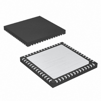
MAX8655ETN+T Maxim Integrated Products, MAX8655ETN+T Datasheet - Page 16

MAX8655ETN+T
Manufacturer Part Number
MAX8655ETN+T
Description
IC STEP-DN REG 25A 56-TQFN-EP
Manufacturer
Maxim Integrated Products
Type
Step-Down (Buck)r
Datasheet
1.MAX8655ETNT.pdf
(23 pages)
Specifications of MAX8655ETN+T
Internal Switch(s)
Yes
Synchronous Rectifier
No
Number Of Outputs
1
Voltage - Output
0.7 ~ 5.5 V
Current - Output
25A
Frequency - Switching
200kHz ~ 1MHz
Voltage - Input
4.5 ~ 25 V
Operating Temperature
-40°C ~ 85°C
Mounting Type
Surface Mount
Package / Case
56-TQFN Exposed Pad
Lead Free Status / RoHS Status
Lead free / RoHS Compliant
Power - Output
-
Lead Free Status / Rohs Status
Lead free / RoHS Compliant
Highly Integrated, 25A, Wide-Input,
Internal MOSFET, Step-Down Regulator
The MAX8655 has an adjustable valley current limit, con-
figurable for foldback with automatic recovery, or con-
stant-current limit with latch-up. To set the constant-
current limit for the latch-up mode, connect a single
resistor R
limit mode, set R
the R
Operating Characteristics section for the required valley
current I
ley current at maximum load (I
To set the current limit for foldback mode, connect a
resistor from ILIM2 to the output (R
resistor from ILIM2 to GND (R
values of R
First, select the percentage of foldback (P
centage corresponds to the current limit when V
equals zero divided by the current limit when V
equals its nominal voltage. A typical value of P
the 15% to 40% range. A lower value of P
lower short-circuit current. The following equations are
used to calculate R
where I
If the resulting value of R
The peak current-limit threshold (V
connected from ILIM1 to GND (R
to the peak voltage across the sensing element (inductor
or current-sense resistor). R
Figure 7. ILIM2 Resistor Connections
16
R
______________________________________________________________________________________
VALLEY
ILIM
ILIM2
VALLEY
ILIM2
2
FOBK
MAX8655
=
vs. Valley Current Limit graph in the Typical
is 5µA.
V
R
OUT
from ILIM2 to GND. For latch-up current-
. I
FOBK
and R
VALLEY
ILIM2
I
ILIM2
ILIM
FOBK
+
LX
(
I
=
ILIM
ILIM2
2
equal to R
Setting the Current Limit
I
ILIM
ILIM2
×
is the value of the inductor val-
and R
P
2
R
FB
ILIM1
×
2
VALLEY
are calculated as follows.
(
LOAD(MAX)
× −
×
R
is negative, increase P
ILIM2
(
ILIM2
V
FO
1
ILIM1
OUT
is calculated as follows:
VALLEY
B B K
TH
P
Valley Current Limit
FB
). See Figure 7. The
×
Peak Current Limit
:
FOBK
) is set by a resistor
R
−
). V
)
FOBK
R
TH
-
VALLEY
), and another
obtained from
1
FB
/
R
R
2
corresponds
FOBK
ILIM2
OUT
). This per-
I
P-P
FB
)
FB
)
)
yields
is in
OUT
OUT
FB
.
This allows a maximum DC output current of:
where R
To ensure maximum output current, use the minimum
value of V
values at the highest expected operating temperature.
The DC resistance of the inductor’s copper wire has a
+0.38%/°C temperature coefficient.
An RC circuit is connected across the inductor (see
Figure 8). The RC time constant is set to be 1.1 to 1.2
times the inductor (L/R
of C9 in the 0.1µF to 0.47µF range, and then calculate
R1 from:
Add a resistor (R2 in Figure 8) to the CS- connection to
minimize input offset error. Calculate the value of R2 as
follows:
• When V
• When V
Figure 8. Current Sense Using the Inductor’s DC Resistance
L
OUT
OUT
is the DC resistance of the inductor.
TH
R
MAX8655
2
R
from each setting, and the maximum R
≥ 2.4V:
< 2.4V:
=
2
=
⎛
⎜
⎝
20
R1 = 1.2L/(R
I
⎛
⎜
⎝
R
LIM
15
µ
ILIM
CS+
CS-
LX
A
µ +
=
A
+
L
1
) time constant. Pick the value
V
=
R
R
15
TH
ILIM
L
7 5
R
20
µ
.
ILIM
10
A x R
32
−
C10
1
µ
×
L
µ
I
A
k
32
P P
×
V
x C9)
1
A
Ω
2
−
TH
R1
10
k
1
x
Ω
µ
10
A
C9
L1
µ
⎞
⎟ ×
⎠
A
⎞
⎟
⎠
R2
R
1
V
OUT
C11
L


