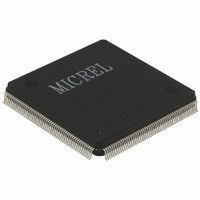
KS8999 Micrel Inc, KS8999 Datasheet - Page 26

KS8999
Manufacturer Part Number
KS8999
Description
IC SWITCH 10/100 9PORT 208PQFP
Manufacturer
Micrel Inc
Specifications of KS8999
Applications
*
Mounting Type
Surface Mount
Package / Case
208-MQFP, 208-PQFP
Fiber Support
Yes
Integrated Led Drivers
Yes
Phy/transceiver Interface
MII/SNI
Power Supply Type
Analog/Digital
Package Type
PQFP
Data Rate (typ)
10/100Mbps
Vlan Support
Yes
Operating Temperature (max)
70C
Operating Temperature (min)
0C
Mounting
Surface Mount
Jtag Support
No
Operating Temperature Classification
Commercial
Lead Free Status / RoHS Status
Contains lead / RoHS non-compliant
For Use With
576-1023 - BOARD EVAL EXPERIMENT FOR KS8999
Lead Free Status / RoHS Status
Not Compliant, Contains lead / RoHS non-compliant
Available stocks
Company
Part Number
Manufacturer
Quantity
Price
Part Number:
KS8999
Manufacturer:
PRX
Quantity:
20 000
KS8999
SNI Interface (7-wire) Operation
The SNI (Serial Network Interface) is compatible with some controllers used for network layer protocol processing. KS8999
acts like a PHY device to external controllers. This interface can be directly connected to these types of devices. The signals
are divided into two groups, one being for transmission and the other being the receive side. The signals involved are described
in the table below.
This interface is a bit wide data interface and therefore runs at the network bit rate (not encoded). An additional signal on the
transmit side indicates when data is valid. Likewise, the receive side has an indicator that conveys when the data is valid.
For half-duplex operation there is a signal that indicate a collision has occurred during transmission.
Programmable Features
Priority Schemes
The KS8999 can determine priority through three different means at the ingress point. The first method is a simple per port
method, the second is via the 802.1p frame tag and the third is by viewing the DSCP (TOS) field in the IPv4 header. Of course
for the priority to be effective, the high and low priority queues must be enabled on the destination port or egress point.
Per Port Method
General priority can be specified on a per port basis. In this type of priority all traffic from the specified input port is considered
high priority in the destination queue. This can be useful in IP phone applications mixed with other data types of traffic where
the IP phone connects to a specific port. The IP phone traffic would be high priority (outbound) to the wide area network. The
inbound traffic to the IP phone is all of the same priority to the IP phone.
802.1p Method
This method works well when used with ports that have mixed data and media flows. The inbound port examines the priority
field in the tag and determines the high or low priority. Priority profiles are setup in the Priority Classification Control in the
EEPROM.
IPv4 DSCP Method
This is another per frame way of determining outbound priority. The DSCP (Differentiated Services Code Point – RFC#2474)
method uses the TOS field in the IP header to determine high and low priority on a per code point basis. Each fully decoded
code point can have either a high or low priority. A larger spectrum of priority flows can be defined with this larger code space.
More specific to implementation, the most significant 6 bits of the TOS field are fully decoded into 64 possibilities, and the
singular code that results is compared against the corresponding bit in the DSCP register. If the register bit is a 1, the priority
is high and if 0, the priority is low.
Other Priority Considerations
When setting up the priority scheme, one should consider other available controls to regulate the traffic. One of these is Priority
Control Scheme (register 2 bits 2-3) which controls the interleaving of high and low priority frames. Options allow from a 2:1
ratio up to a setting that sends all the high priority first. This setting controls all ports globally. Another global feature is Priority
Buffer Reserve (register 2 bit 1). If this is set, there is a 6KB (10%) buffer dedicated to high priority traffic, otherwise if cleared
the buffer is shared between all traffic.
On an individual port basis there are controls that enable DSCP, 802.1p, port based and high/low priority queues. These are
contained in registers 4-12 bits 5-3 and 0. It should be noted that there is a special pin that generally enables the 802.1p priority
for all ports (pin 91). When this pin is active (high) all ports will have the 802.1p priority enabled unless specifically disabled
by EEPROM programming (bit 4 of registers 4-12). Default high priority is a value greater than 4 in the VLAN tag with low priority
being 3 or less.
KS8999
SNI Signal
TXEN
TXD
TXC
COL
CRS
RXD
RXC
Description
Transmit enable
Serial transmit data
Transmit clock
Collision detection
Carrier sense
Serial receive data
Receive clock
Table 2. SNI Signals
26
KS8999
SNI Signal
MTXEN
MTXD[0]
MTXC
MCOL
MRXDV
MRXD[0]
MRXC
KS8999
Input/Output
Input
Input
Output
Output
Output
Output
Output
January 2005
Micrel


