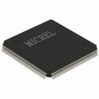
KS8999 Micrel Inc, KS8999 Datasheet - Page 28

KS8999
Manufacturer Part Number
KS8999
Description
IC SWITCH 10/100 9PORT 208PQFP
Manufacturer
Micrel Inc
Specifications of KS8999
Applications
*
Mounting Type
Surface Mount
Package / Case
208-MQFP, 208-PQFP
Fiber Support
Yes
Integrated Led Drivers
Yes
Phy/transceiver Interface
MII/SNI
Power Supply Type
Analog/Digital
Package Type
PQFP
Data Rate (typ)
10/100Mbps
Vlan Support
Yes
Operating Temperature (max)
70C
Operating Temperature (min)
0C
Mounting
Surface Mount
Jtag Support
No
Operating Temperature Classification
Commercial
Lead Free Status / RoHS Status
Contains lead / RoHS non-compliant
For Use With
576-1023 - BOARD EVAL EXPERIMENT FOR KS8999
Lead Free Status / RoHS Status
Not Compliant, Contains lead / RoHS non-compliant
Available stocks
Company
Part Number
Manufacturer
Quantity
Price
Part Number:
KS8999
Manufacturer:
PRX
Quantity:
20 000
KS8999
EEPROM Operation
The EEPROM interface utilizes 2 pins that provide a clock and a serial data path. As part of the initialization sequence, the
KS8999 reads the contents of the EEPROM and loads the values into the appropriate registers. Note that the first two bytes
in the EEPROM must be “55” and “99” respectively for the loading to occur properly. If these first two values are not correct,
all other data will be ignored.
Data start and stop conditions are signaled on the data line as a state transition during clock high time. A high to low transition
indicates start of data and a low to high transition indicates a stop condition. The actual data that traverses the serial line
changes during the clock low time.
The KS8999 EEPROM interface is compatible with the Atmel AT24C01A part. Address A0, A1 and A2 are fixed to 000. Further
timing and data sequences can be found in the Atmel AT24C01A specification.
Optional CPU Interface
Instead of using an EEPROM to program the KS8999, one can use an external processor. To utilize this feature, the CFGMODE
pin (only available on the 208 pin package) needs to pulled low. This makes the KS8999 serial and clock interface into a slave
rather than a master. In this mode, clock and data are sourced from the processor.
Due to timing constraints, the maximum clock speed that the processor can generate is 8MHz. Data timing is referenced to
the rising edge of the clock and are 10ns for setup and 60ns for hold. The processor needs to supply the exact number of clock
cycles and data bits to program the KS8999 properly. KS8999 won’t start until all of the registers are programmed. Bits are
loaded from high order (bit 7) to low order (bit 0) starting with register 0 and finishing with register 53.
KS8999
Register 0:
Register 1 to Register 53: provide clock on bit 7 to bit 0
Skip clock on first bit 7
28
SCL clock cycle: 7
SCL clock cycle: 424
Total SCL clock cycle: 431
January 2005
Micrel


