CDB5378 Cirrus Logic Inc, CDB5378 Datasheet - Page 21
CDB5378
Manufacturer Part Number
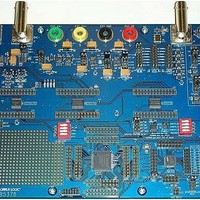
CDB5378
Description
EVALUATION BOARD FOR CS5378
Manufacturer
Cirrus Logic Inc
Datasheets
1.CS5373A-ISZR.pdf
(40 pages)
2.CDB5378.pdf
(16 pages)
3.CDB5378.pdf
(74 pages)
4.CDB5378.pdf
(88 pages)
Specifications of CDB5378
Main Purpose
Seismic Evaluation System
Embedded
Yes, MCU, 8-Bit
Utilized Ic / Part
CS3301A, CS5373A, CS5378
Primary Attributes
Single Digital Filter
Secondary Attributes
Graphical User Interface, SPI™ & USB Interfaces
Processor To Be Evaluated
CS5378
Interface Type
USB
Lead Free Status / RoHS Status
Contains lead / RoHS non-compliant
Lead Free Status / RoHS Status
Lead free / RoHS Compliant, Contains lead / RoHS non-compliant


4. POWER MODES
The CS5373A has five power modes. Modula-
tor mode, AC test modes, and DC test modes
are operational modes, while power down and
sleep mode are non-operational standby
modes.
4.1 Power Down
If MCLK is stopped, an internal loss-of-clock
detection circuit automatically places the
CS5373A into power down. Power down is in-
dependent of the MODE and ATT pin settings,
and is automatically invoked after approxi-
mately 40 µs without an incoming MCLK edge.
In power down the modulator, AC test circuitry
and DC test circuitry are inactive and all out-
puts are high impedance. When used with the
CS5378 digital filter, the CS5373A is in power
down immediately after reset since MCLK is
disabled by default.
4.2 Sleep Mode
With MCLK active, selecting sleep mode
(MODE 7) places the CS5373A into a micro-
power sleep state. In sleep mode the modula-
tor, AC test circuitry and DC test circuitry are
inactive and all outputs are high impedance.
4.3 Modulator Mode
With MCLK active, selecting modulator mode
DS703F2
MODULATOR MODE
MCLK = ON
MODE = 0
Figure 9. Power Mode Diagram
AC TEST MODES
MODE = 1, 2, 3, 6
POWER DOWN
SLEEP MODE
MODE = XXX
MCLK = OFF
MCLK = ON
MCLK = ON
MODE = 7
(MODE 0) enables the CS5373A modulator
and places the AC and DC test circuitry into a
micro-power sleep state with the analog test
outputs high impedance. Following completion
of AC and DC system self-tests, the CS5373A
is typically set into modulator mode for normal
data acquisition.
4.4 AC Test Modes
With MCLK and TDATA active, selecting an
AC test mode (MODE 1, 2, 3, 6) enables the
modulator and causes the DAC to output AC
waveforms on the analog test outputs. AC test
modes use the low-power ΔΣ DAC circuitry in
the CS5373A to create precision differential or
common mode analog AC output signals from
the encoded digital test bit stream (TBS) input.
4.5 DC Test Modes
With MCLK active, selecting a DC test mode
(MODE 4, 5) enables the modulator and
causes the DAC to generate precision DC volt-
ages on the analog test outputs. DC test
modes use switch-capacitor level-shifting buf-
fer circuitry in the CS5373A to create differen-
tial or common mode DC analog output
voltages from the voltage reference input.
DC TEST MODES
MODE = 4, 5
MCLK = ON
CS5373A
21
Related parts for CDB5378
Image
Part Number
Description
Manufacturer
Datasheet
Request
R

Part Number:
Description:
Development Kit
Manufacturer:
Cirrus Logic Inc
Datasheet:
Part Number:
Description:
Development Kit
Manufacturer:
Cirrus Logic Inc
Datasheet:


Part Number:
Description:
High-efficiency PFC + Fluorescent Lamp Driver Reference Design
Manufacturer:
Cirrus Logic Inc
Datasheet:
Part Number:
Description:
Development Kit
Manufacturer:
Cirrus Logic Inc
Datasheet:
Part Number:
Description:
Development Kit
Manufacturer:
Cirrus Logic Inc
Datasheet:

Part Number:
Description:
Development Kit
Manufacturer:
Cirrus Logic Inc
Datasheet:
Part Number:
Description:
Development Kit
Manufacturer:
Cirrus Logic Inc
Datasheet:
Part Number:
Description:
Development Kit
Manufacturer:
Cirrus Logic Inc
Datasheet:
Part Number:
Description:
Development Kit
Manufacturer:
Cirrus Logic Inc
Datasheet:

Part Number:
Description:
EVALUATION BOARD FOR CS8427
Manufacturer:
Cirrus Logic Inc
Datasheet:

Part Number:
Description:
BOARD EVAL FOR CS8416 RCVR
Manufacturer:
Cirrus Logic Inc
Datasheet:

Part Number:
Description:
EVALUATION BOARD FOR CS8420
Manufacturer:
Cirrus Logic Inc
Datasheet:

Part Number:
Description:
KIT DEVELOPMENT EP9315 ARM9
Manufacturer:
Cirrus Logic Inc
Datasheet:

Part Number:
Description:
KIT DEVELOPMENT EP9302 ARM9
Manufacturer:
Cirrus Logic Inc
Datasheet: