CDB5378 Cirrus Logic Inc, CDB5378 Datasheet - Page 34
CDB5378
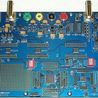
Manufacturer Part Number
CDB5378
Description
EVALUATION BOARD FOR CS5378
Manufacturer
Cirrus Logic Inc
Datasheets
1.CS5373A-ISZR.pdf
(40 pages)
2.CDB5378.pdf
(16 pages)
3.CDB5378.pdf
(74 pages)
4.CDB5378.pdf
(88 pages)
Specifications of CDB5378
Main Purpose
Seismic Evaluation System
Embedded
Yes, MCU, 8-Bit
Utilized Ic / Part
CS3301A, CS5373A, CS5378
Primary Attributes
Single Digital Filter
Secondary Attributes
Graphical User Interface, SPI™ & USB Interfaces
Processor To Be Evaluated
CS5378
Interface Type
USB
Lead Free Status / RoHS Status
Contains lead / RoHS non-compliant
Lead Free Status / RoHS Status
Lead free / RoHS Compliant, Contains lead / RoHS non-compliant


9.4 SCR Latch-up
The VA- pin is tied to the CS5373A CMOS
substrate and must always be the most-nega-
tive voltage applied to the device to ensure
SCR latch-up does not occur. In general,
latch-up may occur when any pin voltage ex-
ceeds
Absolute Maximum Ratings
It is recommended to connect the VA- power
supply to system ground (GND) with a re-
verse-biased Schottky diode. At power up, if
the VA+ power supply ramps before the VA-
supply is established, the VA- pin voltage
could be pulled above ground potential
through the CS5373A device. If the VA- supply
is pulled 0.7 V or more above GND, SCR
latch-up can occur. A reverse-biased Schottky
diode will clamp the VA- voltage a maximum of
0.3 V above ground to ensure SCR latch-up
does not occur at power up.
9.5 DC-DC Converters
Many low-frequency measurement systems
are battery powered and utilize DC-DC con-
10.TERMINOLOGY
•
•
•
•
•
34
Signal-to-Noise Ratio (Dynamic Range) - Ratio of the rms magnitude of the full-scale signal to the integrated
rms noise from DC to 400 Hz. The following formula is used to calculate SNR:
Total Harmonic Distortion - Ratio of the power of the fundamental frequency to the sum of the powers of all
harmonic frequencies from DC to 400 Hz. The following formula is used to calculate THD:
Full-scale Bandwidth - The bandwidth in which the converter can generate a full-scale signal while maintaining
performance specifications.
Impulse Amplitude - The maximum amplitude of the output signal beyond the full-scale bandwidth.
Differential Output Level - The voltage between the analog output pins of the device.
the
limits
THD = 10log
SNR = 20log
specified
table.
(
sum of the powers of the harmonic frequencies
(
in
rms magnitude of full scale signal
rms magnitude of noise floor
power of the fundamental frequency
the
verters to efficiently generate power supply
voltages. To minimize interference effects, op-
erate the DC-DC converter at a frequency
which is rejected by the digital filter, or operate
it synchronous to the MCLK rate.
A synchronous DC-DC converter whose oper-
ating frequency is derived from MCLK will the-
oretically minimize the potential for “beat
frequencies” to appear in the measurement
bandwidth. However this requires the source
clock to remain jitter-free within the DC-DC
converter circuitry. If clock jitter can occur with-
in the DC-DC converter (as in a PLL-based ar-
chitecture),
synchronous DC-DC converter whose switch-
ing frequency is rejected by the digital filter.
During PCB layout, do not place high-current
DC-DC converters near sensitive analog com-
ponents. Carefully routing a separate DC-DC
“star” ground will help isolate noisy switching
currents away from the sensitive analog com-
ponents.
it’s
better
(
to
(
use
CS5373A
a
DS703F2
non-
Related parts for CDB5378
Image
Part Number
Description
Manufacturer
Datasheet
Request
R

Part Number:
Description:
Development Kit
Manufacturer:
Cirrus Logic Inc
Datasheet:
Part Number:
Description:
Development Kit
Manufacturer:
Cirrus Logic Inc
Datasheet:


Part Number:
Description:
High-efficiency PFC + Fluorescent Lamp Driver Reference Design
Manufacturer:
Cirrus Logic Inc
Datasheet:
Part Number:
Description:
Development Kit
Manufacturer:
Cirrus Logic Inc
Datasheet:
Part Number:
Description:
Development Kit
Manufacturer:
Cirrus Logic Inc
Datasheet:

Part Number:
Description:
Development Kit
Manufacturer:
Cirrus Logic Inc
Datasheet:
Part Number:
Description:
Development Kit
Manufacturer:
Cirrus Logic Inc
Datasheet:
Part Number:
Description:
Development Kit
Manufacturer:
Cirrus Logic Inc
Datasheet:
Part Number:
Description:
Development Kit
Manufacturer:
Cirrus Logic Inc
Datasheet:

Part Number:
Description:
EVALUATION BOARD FOR CS8427
Manufacturer:
Cirrus Logic Inc
Datasheet:

Part Number:
Description:
BOARD EVAL FOR CS8416 RCVR
Manufacturer:
Cirrus Logic Inc
Datasheet:

Part Number:
Description:
EVALUATION BOARD FOR CS8420
Manufacturer:
Cirrus Logic Inc
Datasheet:

Part Number:
Description:
KIT DEVELOPMENT EP9315 ARM9
Manufacturer:
Cirrus Logic Inc
Datasheet:

Part Number:
Description:
KIT DEVELOPMENT EP9302 ARM9
Manufacturer:
Cirrus Logic Inc
Datasheet: