CDB5378 Cirrus Logic Inc, CDB5378 Datasheet - Page 29
CDB5378
Manufacturer Part Number
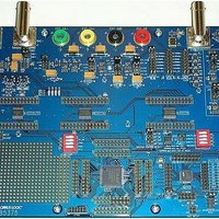
CDB5378
Description
EVALUATION BOARD FOR CS5378
Manufacturer
Cirrus Logic Inc
Datasheets
1.CS5373A-ISZR.pdf
(40 pages)
2.CDB5378.pdf
(16 pages)
3.CDB5378.pdf
(74 pages)
4.CDB5378.pdf
(88 pages)
Specifications of CDB5378
Main Purpose
Seismic Evaluation System
Embedded
Yes, MCU, 8-Bit
Utilized Ic / Part
CS3301A, CS5373A, CS5378
Primary Attributes
Single Digital Filter
Secondary Attributes
Graphical User Interface, SPI™ & USB Interfaces
Processor To Be Evaluated
CS5378
Interface Type
USB
Lead Free Status / RoHS Status
Contains lead / RoHS non-compliant
Lead Free Status / RoHS Status
Lead free / RoHS Compliant, Contains lead / RoHS non-compliant


The -3 dB corner of the input anti-alias filter is
nominally set to the internal analog sampling
rate divided by 64, which itself is a division by
4 of the MCLK input rate.
Figure 14 illustrates the CS5373A modulator
analog connections with input anti-alias filter
components. Filter components on the rough
and fine pins should be identical values for op-
timum performance, with the capacitor values
a minimum of 0.02 μF. The rough input can
use either X7R or C0G type capacitors, while
the fine input requires C0G type capacitors for
optimal linearity. Using X7R type capacitors on
the fine analog inputs will degrade total har-
monic distortion significantly.
The CS3301A/02A differential amplifiers are
designed with separate rough and fine analog
outputs (OUTR±, OUTF±) that match the
rough and fine inputs to the modulator (INR±,
INF±). Internal anti-alias series resistors are
NOT included in the amplifier analog outputs,
therefore external differential capacitors as
well as 680 Ω resistors are required to create
the anti-alias RC filters.
7.2 DAC Output Attenuation
The CS5373A test DAC has seven analog out-
put attenuation settings from 1/1 to 1/64 se-
lected with the ATT2, ATT1, and ATT0 pins.
When enabled, attenuation is applied to both
the OUT± and BUF± differential analog out-
puts. At 1/64 attenuation in AC Common Mode
(MODE 6) there is no output signal amplitude
due to the attenuator architecture.
The OUT± pins connect directly into the inter-
nal attenuator resistors and so attenuation ac-
curacy is highly sensitive to load impedance
DS703F2
•
•
•
•
MCLK Frequency = 2.048 MHz
Sampling Frequency = MCLK / 4 = 512 kHz
-3 dB Filter Corner = Sample Freq / 64 = 8 kHz
RC filter = 8 kHz = 1 / [ 2π * (2 * R
series
) * C
diff
)]
on the OUT± pins. Loading on the BUF± pins
does not affect attenuator accuracy.
The attenuation settings of CS5373A match
the gain ranges of the CS3301A/02A differen-
tial amplifiers to enable full-scale testing at all
gain ranges. The CS3301A/02A amplifier gain
settings (GAIN) are decoded identical to the
CS5373A attenuator settings (ATT) and so
can share GPIO control signals from the
CS5378 digital filter.
7.3 DAC OUT± Precision Output
The test DAC OUT± pins are precision differ-
ential analog outputs for testing the high-per-
formance electronics measurement channel.
These precision outputs have higher perfor-
mance specifications than the BUF± outputs,
but with a much higher sensitivity to external
loading. Excessive resistive or capacitive load-
ing on the OUT± pins will degrade the analog
performance characteristics of the test DAC in
all operational modes.
The OUT± precision output is optimized for di-
rect connection to the CS3301A/02A amplifier
differential inputs, which have very high input
impedance. These amplifiers include a pin-
controlled input multiplexer to switch between
an internal differential termination for noise
Selection ATT[2:0]
Figure 15. DAC Output Attenuation Settings
0
1
2
3
4
5
6
7
0 0 0
0 0 1
0 1 0
0 1 1
1 0 0
1 0 1
1 1 0
1 1 1
Attenuation
reserved
1/16
1/32
1/64
1/1
1/2
1/4
1/8
CS5373A
-12.04 dB
-18.06 dB
-24.08 dB
-30.10 dB
-36.12 dB
reserved
-6.02 dB
0 dB
dB
29
Related parts for CDB5378
Image
Part Number
Description
Manufacturer
Datasheet
Request
R

Part Number:
Description:
Development Kit
Manufacturer:
Cirrus Logic Inc
Datasheet:
Part Number:
Description:
Development Kit
Manufacturer:
Cirrus Logic Inc
Datasheet:


Part Number:
Description:
High-efficiency PFC + Fluorescent Lamp Driver Reference Design
Manufacturer:
Cirrus Logic Inc
Datasheet:
Part Number:
Description:
Development Kit
Manufacturer:
Cirrus Logic Inc
Datasheet:
Part Number:
Description:
Development Kit
Manufacturer:
Cirrus Logic Inc
Datasheet:

Part Number:
Description:
Development Kit
Manufacturer:
Cirrus Logic Inc
Datasheet:
Part Number:
Description:
Development Kit
Manufacturer:
Cirrus Logic Inc
Datasheet:
Part Number:
Description:
Development Kit
Manufacturer:
Cirrus Logic Inc
Datasheet:
Part Number:
Description:
Development Kit
Manufacturer:
Cirrus Logic Inc
Datasheet:

Part Number:
Description:
EVALUATION BOARD FOR CS8427
Manufacturer:
Cirrus Logic Inc
Datasheet:

Part Number:
Description:
BOARD EVAL FOR CS8416 RCVR
Manufacturer:
Cirrus Logic Inc
Datasheet:

Part Number:
Description:
EVALUATION BOARD FOR CS8420
Manufacturer:
Cirrus Logic Inc
Datasheet:

Part Number:
Description:
KIT DEVELOPMENT EP9315 ARM9
Manufacturer:
Cirrus Logic Inc
Datasheet:

Part Number:
Description:
KIT DEVELOPMENT EP9302 ARM9
Manufacturer:
Cirrus Logic Inc
Datasheet: