KDC5514EVALZ Intersil, KDC5514EVALZ Datasheet - Page 22
KDC5514EVALZ
Manufacturer Part Number
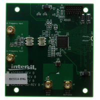
KDC5514EVALZ
Description
DAUGHTER CARD FOR KAD5514
Manufacturer
Intersil
Series
FemtoCharge™r
Datasheets
1.KAD5514P-25Q72.pdf
(34 pages)
2.KMB-001LEVALZ.pdf
(7 pages)
3.KDC5514EVALZ.pdf
(9 pages)
Specifications of KDC5514EVALZ
Number Of Adc's
1
Number Of Bits
14
Sampling Rate (per Second)
250M
Data Interface
Parallel
Inputs Per Adc
1 Differential
Input Range
1.47 Vpp
Power (typ) @ Conditions
429mW @ 250MSPS
Voltage Supply Source
Single Supply
Operating Temperature
-40°C ~ 85°C
Utilized Ic / Part
KAD5514P-25, KMB001 Motherboard
For Use With
KMB001LEVAL - MOTHERBOARD FOR LVDS ADC CARD
Lead Free Status / RoHS Status
Lead free / RoHS Compliant
Other names
KDC5514EVAL
KDC5514EVAL
KDC5514EVAL
Available stocks
Company
Part Number
Manufacturer
Quantity
Price
Company:

Part Number:
KDC5514EVALZ
Manufacturer:
Intersil
Quantity:
5


Mapping of the input voltage to the various data formats is
shown in Table 5.
SCLK
SDIO
SCLK
SDIO
CSB
CSB
FIGURE 34. GRAY CODE TO BINARY CONVERSION
GRAY CODE
BINARY
13
13
R/W
A0
12
12
22
W1
A1
11
11
W0
A2
• • • •
• • • •
• • • •
• • • •
A12
A11
FIGURE 35. MSB-FIRST ADDRESSING
FIGURE 36. LSB-FIRST ADDRESSING
A11
A12
1
1
A10
W0
0
0
KAD5514P
W1
A1
R/W
A0
Serial Peripheral Interface
A serial peripheral interface (SPI) bus is used to facilitate
configuration of the device and to optimize performance. The
SPI bus consists of chip select (CSB), serial clock (SCLK)
serial data input (SDI), and serial data input/output (SDIO).
The maximum SCLK rate is equal to the ADC sample rate
(f
divided by 66 for reads. At f
SCLK is 15.63MHz for writing and 3.79MHz for read
operations. There is no minimum SCLK rate.
The following sections describe various registers that are
used to configure the SPI or adjust performance or functional
parameters. Many registers in the available address space
(0x00 to 0xFF) are not defined in this document. Additionally,
within a defined register there may be certain bits or bit
combinations that are reserved. Undefined registers and
undefined values within defined registers are reserved and
should not be selected. Setting any reserved register or value
may produce indeterminate results.
–Full Scale
–Full Scale
+Full Scale
+Full Scale
SAMPLE
VOLTAGE OFFSET BINARY
Mid–Scale
+ 1LSB
– 1LSB
INPUT
D0
D7
TABLE 5. INPUT VOLTAGE TO OUTPUT CODE MAPPING
) divided by 16 for write operations and f
D1
D6
000 00 000 00 00 00 100 00 000 00 00 00 000 00 000 00 00 00
000 00 000 00 00 01 100 00 000 00 00 01 000 00 000 00 00 01
100 00 000 00 00 00 000 00 000 00 00 00 110 00 000 00 00 00
111 11 111 11 11 10
111 11 111 11 11 11
D5
D2
D3
D4
SAMPLE
D4
D3
COMPLEMENT
011 11 111 11 11 10
011 11 111 111 11 1
TWO’S
D5
D2
= 250MHz, maximum
D1D
D6
September 10, 2009
100 00 000 00 00 01
100 00 000 00 00 00
D7
GRAY CODE
0
SAMPLE
FN6804.2
Related parts for KDC5514EVALZ
Image
Part Number
Description
Manufacturer
Datasheet
Request
R

Part Number:
Description:
DAUGHTER CARD FOR KAD5514
Manufacturer:
Intersil
Datasheet:

Part Number:
Description:
Intersil Corporation [CMOS Serial Controller Interface]
Manufacturer:
Intersil Corporation
Datasheet:
Part Number:
Description:
Manufacturer:
Intersil Corporation
Datasheet:
Part Number:
Description:
357-036-542-201 CARDEDGE 36POS DL .156 BLK LOPRO
Manufacturer:
Intersil Corporation
Datasheet:
Part Number:
Description:
1024-Word x 4-Bit LSI Static RAM
Manufacturer:
Intersil Corporation
Datasheet:
Part Number:
Description:
General Purpose NPN Transistor Arrays FN341.4
Manufacturer:
Intersil Corporation
Datasheet:
Part Number:
Description:
CMOS 16-Bit Microprocessor
Manufacturer:
Intersil Corporation
Datasheet:
Part Number:
Description:
Manufacturer:
Intersil Corporation
Datasheet:
Part Number:
Description:
Manufacturer:
Intersil Corporation
Datasheet:
Part Number:
Description:
Manufacturer:
Intersil Corporation
Datasheet:
Part Number:
Description:
Manufacturer:
Intersil Corporation
Datasheet:
Part Number:
Description:
CMOS 6-Bit Latch and Decoder Memory Interfaces
Manufacturer:
Intersil Corporation
Datasheet:
Part Number:
Description:
CA3046General Purpose NPN Transistor Arrays
Manufacturer:
Intersil Corporation
Datasheet:
Part Number:
Description:
Manufacturer:
Intersil Corporation
Datasheet:
Part Number:
Description:
TR909 DLC/FLC SLIC with Low Power Standby
Manufacturer:
Intersil Corporation
Datasheet: