KDC5514EVALZ Intersil, KDC5514EVALZ Datasheet - Page 6
KDC5514EVALZ
Manufacturer Part Number
KDC5514EVALZ
Description
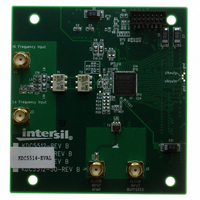
DAUGHTER CARD FOR KAD5514
Manufacturer
Intersil
Series
FemtoCharge™r
Datasheets
1.KAD5514P-25Q72.pdf
(34 pages)
2.KMB-001LEVALZ.pdf
(7 pages)
3.KDC5514EVALZ.pdf
(9 pages)
Specifications of KDC5514EVALZ
Number Of Adc's
1
Number Of Bits
14
Sampling Rate (per Second)
250M
Data Interface
Parallel
Inputs Per Adc
1 Differential
Input Range
1.47 Vpp
Power (typ) @ Conditions
429mW @ 250MSPS
Voltage Supply Source
Single Supply
Operating Temperature
-40°C ~ 85°C
Utilized Ic / Part
KAD5514P-25, KMB001 Motherboard
For Use With
KMB001LEVAL - MOTHERBOARD FOR LVDS ADC CARD
Lead Free Status / RoHS Status
Lead free / RoHS Compliant
Other names
KDC5514EVAL
KDC5514EVAL
KDC5514EVAL
Available stocks
Company
Part Number
Manufacturer
Quantity
Price
Company:

Part Number:
KDC5514EVALZ
Manufacturer:
Intersil
Quantity:
5


Electrical Specifications
NOTES:
Intermodulation
Distortion
Word Error Rate
Full Power Bandwidth
4. Digital Supply Current is dependent upon the capacitive loading of the digital outputs. I
5. See Nap /Sleep Mode description on page 21 for more detail.
6. The DLL Range setting must be changed for low speed operation. See the “Serial Peripheral Interface” on page 22 for more detail.
7. Parameters with MIN and/or MAX limits are 100% production tested at their worst case temperature extreme (+85°C).
Digital Specifications
INPUTS
Input Current High
(SDIO, RESETN)
Input Current Low
(SDIO, RESETN)
Input Voltage High
(SDIO, RESETN)
Input Voltage Low
(SDIO, RESETN)
Input Current High (OUTMODE,
NAPSLP, CLKDIV, OUTFMT)
(Note 8)
Input Current Low (OUTMODE,
NAPSLP, CLKDIV, OUTFMT)
Input Capacitance
LVDS OUTPUTS
Differential Output Voltage
Output Offset Voltage
Output Rise Time
Output Fall Time
CMOS OUTPUTS
Voltage Output High
Voltage Output Low
Output Rise Time
Output Fall Time
PARAMETER
PARAMETER
SYMBOL
FPBW
WER
IMD
All specifications apply under the following conditions unless otherwise noted: AVDD = 1.8V, OVDD = 1.8V,
T
(per speed grade). (Continued)
A
6
= -40°C to +85°C (typical specifications at +25°C), A
f
f
IN
IN
CONDITIONS
= 70MHz
= 170MHz
SYMBOL
V
V
V
C
V
V
I
I
V
I
I
t
t
t
t
IH
IH
OS
OH
IL
IL
OL
R
F
R
F
IH
DI
IL
T
V
V
3mA Mode
3mA Mode
I
I
OH
OL
MIN
IN
IN
KAD5514P-25
CONDITIONS
= 1mA
= 1.8V
= 0V
= -500µA
(Note 7)
10
-89.2
-91.4
TYP
950
-12
KAD5514P
MAX MIN
KAD5514P-21
OVDD - 0.3
(Note 7)
10
-92.3
-86.9
1.17
MIN
TYP
950
-25
-40
950
15
0
-12
OVDD
IN
MAX MIN
= -1dBFS, f
specifications apply for 10pF load on each digital output.
OVDD - 0.1
KAD5514P-17
TYP
620
965
500
500
-12
0.1
1.8
1.4
25
25
1
3
SAMPLE
(Note 7)
10
-94.5
-91.7
TYP
950
-12
= Maximum Conversion Rate
MAX MIN
MAX
980
-15
.63
0.3
10
40
-5
KAD5514P-12
(Note 7)
10
-94.9
-85.7
TYP
950
-12
September 10, 2009
MAX
UNITS
mV
mV
µA
µA
µA
µA
pF
ps
ps
ns
ns
V
V
V
V
P-P
FN6804.2
UNITS
dBFS
dBFS
MHz
Related parts for KDC5514EVALZ
Image
Part Number
Description
Manufacturer
Datasheet
Request
R

Part Number:
Description:
DAUGHTER CARD FOR KAD5514
Manufacturer:
Intersil
Datasheet:

Part Number:
Description:
Intersil Corporation [CMOS Serial Controller Interface]
Manufacturer:
Intersil Corporation
Datasheet:
Part Number:
Description:
Manufacturer:
Intersil Corporation
Datasheet:
Part Number:
Description:
357-036-542-201 CARDEDGE 36POS DL .156 BLK LOPRO
Manufacturer:
Intersil Corporation
Datasheet:
Part Number:
Description:
1024-Word x 4-Bit LSI Static RAM
Manufacturer:
Intersil Corporation
Datasheet:
Part Number:
Description:
General Purpose NPN Transistor Arrays FN341.4
Manufacturer:
Intersil Corporation
Datasheet:
Part Number:
Description:
CMOS 16-Bit Microprocessor
Manufacturer:
Intersil Corporation
Datasheet:
Part Number:
Description:
Manufacturer:
Intersil Corporation
Datasheet:
Part Number:
Description:
Manufacturer:
Intersil Corporation
Datasheet:
Part Number:
Description:
Manufacturer:
Intersil Corporation
Datasheet:
Part Number:
Description:
Manufacturer:
Intersil Corporation
Datasheet:
Part Number:
Description:
CMOS 6-Bit Latch and Decoder Memory Interfaces
Manufacturer:
Intersil Corporation
Datasheet:
Part Number:
Description:
CA3046General Purpose NPN Transistor Arrays
Manufacturer:
Intersil Corporation
Datasheet:
Part Number:
Description:
Manufacturer:
Intersil Corporation
Datasheet:
Part Number:
Description:
TR909 DLC/FLC SLIC with Low Power Standby
Manufacturer:
Intersil Corporation
Datasheet: