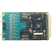
EVAL-AD7689EDZ Analog Devices Inc, EVAL-AD7689EDZ Datasheet - Page 9

EVAL-AD7689EDZ
Manufacturer Part Number
EVAL-AD7689EDZ
Description
BOARD EVAL AD7689
Manufacturer
Analog Devices Inc
Series
PulSAR®r
Specifications of EVAL-AD7689EDZ
Number Of Adc's
1
Number Of Bits
16
Sampling Rate (per Second)
250k
Data Interface
Serial
Inputs Per Adc
8 Single Ended
Input Range
±VREF
Power (typ) @ Conditions
12.5mW @ 250kSPS, 5 V
Voltage Supply Source
Single Supply
Operating Temperature
-40°C ~ 85°C
Utilized Ic / Part
AD7689
Silicon Manufacturer
Analog Devices
Application Sub Type
ADC
Kit Application Type
Data Converter
Silicon Core Number
AD7689
Lead Free Status / RoHS Status
Lead free / RoHS Compliant
Preliminary Technical Data
ADC CONFIGURATION
The ADC needs to be configured for input configuration,
reference, channel to be converted, temperature sensor, and on-
chip low pass (LP) filter (optional) for full bandwidth (BW) or
¼ BW. These next figures show the pull down configurations
available. Note the default value when the program is started is
indicated by the √; or CFG writing enabled, unipolar INn to
GND, CH0, full BW, and external reference. Note that after
updating the CFG, the first conversion (when using burst
mode) will be of the last configuration since the ADC has a 1-
depp delay for the CFG.
Figure 3 shows the default values.
Figure 4 details CFG Write Enabled/Disabled. When enabled,
the MSB of the CFG is set high. When disabled the MSB is set
low thus the remaining 13 bits are ignored.
Figure 5 details the inputs (IN0-IN7) configuration and channel
selection. Refer to the datasheet for more information about the
input configure-ations. Note that in the bipolar mode, the input,
IN+ and COM (or IN-) must be centered around VREF/2.
Figure 4. CGF Enable/Disable Selection
Figure 3. Default CFG
Rev. PrD | Page 9 of 26
Figure 6 details the bandwidth selection of the 1-pole low pass
filter, which can reduce the noise from the amplifier circuit, if
desired. Note that the throughout of the converter must also
reduce to ¼ of the maximum when setting to ¼ BW.
Figure 7 details the reference selection. Note that the TEMP
sensor can be used with an external reference. The Temp sensor
can be used to monitor the temperature of the ADC and the
output is straight binary and referenced to the ADC GND. The
displayed results should be in Volts format as opposed to Hex.
Figure 5. Input Configuration/Channel Selection
Figure 7. Reference Selection
Figure 6.BW Select
EVAL-AD76MUXEDZ


