CDB5534U Cirrus Logic Inc, CDB5534U Datasheet

CDB5534U
Specifications of CDB5534U
Related parts for CDB5534U
CDB5534U Summary of contents
Page 1
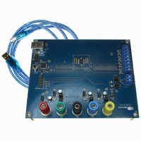
... AIN4- VREF+ VREF- http://www.cirrus.com General Description The CDB5534U is an inexpensive tool designed to eval- uate the functionality and performance of the CS5534. The CS5534 datasheet should be read and consulted when using the CDB5534U evaluation board. The evaluation board includes a C8051F320 microcon- troller with a USB interface. The microcontroller controls ...
Page 2
... Figure 1. Analog Section ................................................................................................................. 6 Figure 2. Digital Section .................................................................................................................. 7 Figure 3. Power Supply ................................................................................................................... 8 Figure 4. CDB5534U Start-Up Screen .......................................................................................... 10 Figure 5. CDB5534U Setup Window............................................................................................. 11 Figure 6. CDB5534U Channel Setup Register Window ................................................................ 12 Figure 7. CDB5534U Calibration Window ..................................................................................... 13 Figure 8. CDB5534U Data Collection Window.............................................................................. 14 Figure 9. CDB5534U Configuration Window................................................................................. 15 Figure 10. Top Silkscreen ............................................................................................................. 18 Figure 11. Top Side Layout ........................................................................................................... 19 Figure 12 ...
Page 3
... Hz, 400 Hz, 480 Hz, 800 Hz, 960 Hz, 1.6 kHz, 1.92 kHz, 3.2 kHz and 3.84 kHz (XIN = 4.9152 MHz). The CDB5534U is shipped with a CS5534 device soldered at U2. However, the CS5531, CS5532, or CS5533 can be soldered in this same location. The CDB5534U software supports all four devices. ...
Page 4
... Note that the VA- supply should be connected to ground when powering the CDB5534U from a single +5 V analog supply. VD+ supplies the digital section of the ADC and level shifters. Header J15 allows the VD+ supply to be sourced from the VD+ binding post (J5), ...
Page 5
... V binding post (J3), or the regulated +3.3 V supply derived from the microcontroller. The +5 V bind- ing post supplies the microcontrollers internal regulator. DS289DB6 CDB5534U 5 ...
Page 6
... CDB5534U DS289DB6 ...
Page 7
... DS289DB6 CDB5534U 7 ...
Page 8
... CDB5534U DS289DB6 ...
Page 9
... Installing the USB Drivers 1. Apply power to the CDB5534U. Press and release the Reset switch, S1. 2. Use the included USB cable to connect the CDB5534U to the PC. The PC operating system should automatically launch the Found New Hardware wizard. 3. From the installation wizard, select Install from a list or specific location (Advanced). Select Search for the best driver in these locations ...
Page 10
... The user has two options for the data source: USB and File. If the USB setup is selected, the evaluation software will be ready to communicate with the CDB5534U via the USB connection. At this point, the Part menu item is active and the appropriate CS553x device can be selected. If the File source is selected, the evaluation software will prompt the user to select the appropriate data file ...
Page 11
... After a reset, the registers will all return to their default values as discussed in the CS5534 datasheet. Read Data: This button will instruct the ADC to begin performing repeated single (fully-settled) conver- sions on the setup channel specified by the Setup Register box. The results of the most recent conversion DS289DB6 Figure 5. CDB5534U Setup Window CDB5534U 11 ...
Page 12
... The currently displayed CSR can be modified by either typing a value directly in the Hexadecimal: box or by changing the decoded values in the individual Setup boxes. Figure 6. CDB5534U Channel Setup Register Window Offset / Gain Registers: In the Offset Registers / Gain Registers box, the offset and gain registers for all channels are displayed in hexadecimal ...
Page 13
... Pull down the System Gain box, and select the setup number you want to use to calibrate the channel. 3) When the calibration is complete, the screen will automatically update the offset and gain registers with the new values. DS289DB6 Figure 7. CDB5534U Calibration Window CDB5534U 13 ...
Page 14
... FFT, and histogram plots. The Data Collection Window is accessi- ble through the Window option pressing F3. Figure 8. CDB5534U Data Collection Window Time Domain / FFT / Histogram Selector: This menu selects the type of data processing to perform on the collected data and display in the plot area. Refer to the section on Analyzing Data for more information. ...
Page 15
... Increasing this number may allow the user to view histograms with larger input ranges. Crystal Frequency: The CDB5534U evaluation board comes equipped with a 4.9152 MHz crystal. If the user chooses to replace this with a crystal of a different frequency, the number in this box can be modified to provide more accurate timing and FFT information ...
Page 16
... Setup and the number of samples being collected, this process may take several min- utes. The process can be terminated by pressing the Stop button, but if this is done, the user should also press Reset on the CDB5534U board to bring the microcontroller out of the collection routines. ...
Page 17
... COUNT: Displays current x-position of the cursor on the time domain display. MAGNITUDE: Displays current y-position of the cursor on the time domain display. MAXIMUM: Indicator for the maximum value of the collected data set. MINIMUM: Indicator for the minimum value of the collected data set. DS289DB6 CDB5534U 17 ...
Page 18
... BOARD LAYOUT 18 CDB5534U DS289DB6 ...
Page 19
... DS289DB6 CDB5534U 19 ...
Page 20
... CDB5534U DS289DB6 ...
Page 21
... DS289DB6 CDB5534U 21 ...
Page 22
... Cirrus Logic, Cirrus, and the Cirrus Logic logo designs are trademarks of Cirrus Logic, Inc. All other brand and product names in this document may be trademarks or service marks of their respective owners. Windows is a registered trademark of Microsoft Corporation. SPI is a trademark of Motorola, Inc. Microwire is a trademark of National Semiconductor Corporation. IBM is a registered trademark of International Business Machines Corporation. 22 CDB5534U DS289DB6 ...


